Constant-voltage charger circuit of communication equipment
A technology of communication equipment and charger, which is applied in the direction of battery disconnection circuit, battery circuit device, collector, etc., can solve the problems of single charger function, unable to stabilize voltage supply, charging intelligent control and adjustment, etc., to achieve multiple functions and stability The effect of charging voltage and ease of use
Inactive Publication Date: 2021-01-29
陈建明
View PDF0 Cites 0 Cited by
- Summary
- Abstract
- Description
- Claims
- Application Information
AI Technical Summary
Problems solved by technology
[0003] Most of the existing communication equipment chargers have a single function, and cannot intelligently control and adjust the charging while taking into account the stable voltage supply, so it needs to be improved
Method used
View moreImage
Smart ImageViewing Examples


Examples
Embodiment 2
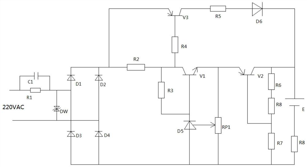
[0020] Embodiment 2, on the basis of embodiment 1, resistor R6 and resistor R8 respectively adopt positive and negative temperature coefficient thermistors, which can effectively reduce the influence of temperature on the circuit, especially the temperature caused by the rise of circuit temperature during charging. influences.
Login to View More PUM
 Abstract
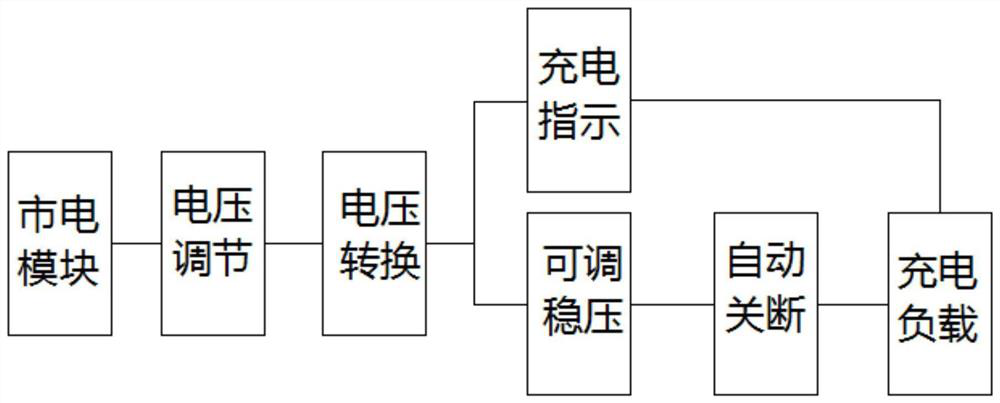
The invention discloses a constant-voltage charger circuit of communication equipment. The constant-voltage charger circuit comprises a resistor R1, a capacitor C1, a triode V1, a triode V2 and a triode V3, and one end of the resistor R1 is connected with one end of the capacitor C1 and one end of 220V alternating current, and the other end of the resistor R1 is connected with the other end of thecapacitor C1, the anode of a diode D1 and a TVS diode DW; and the other end of the TVS diode DW is connected with the anode of a diode D2, the cathode of a diode D4 and the other end of the 220V alternating current. The constant-voltage charger circuit of the communication equipment not only can automatically disconnect the circuit after the charging is completed, but also can effectively protectand stabilize the charging voltage in the charging process, and is provided with the charging warning lamp as a charging indication, so that the constant-voltage charger circuit of the communicationequipment is multifunctional and convenient to use.
Description
technical field [0001] The invention relates to the technical field of charging, in particular to a constant-voltage charger circuit for communication equipment. Background technique [0002] Since the lead-acid battery was invented 150 years ago, it has always had an absolute advantage in chemical energy batteries. This is because of its low price, reliable use, suitable for large current discharge, and wide range of ambient temperature. Lead-acid batteries play an important role in transportation, communications, military, navigation, aviation, photovoltaic power generation and other fields. In particular, the successful development of maintenance-free sealed lead-acid batteries has made the application of lead-acid batteries more extensive. As we all know, the service life of the battery is directly related to the performance of its charger. [0003] Most of the existing communication equipment chargers have single functions, and cannot intelligently control and adjust...
Claims
Login to View More Application Information
Patent Timeline
 Patent Type & Authority Applications(China)
IPC IPC(8): H02J7/04H02J7/00
CPCH02J7/0031H02J7/04H02J7/007182
Inventor 陈建明
Owner 陈建明
Features
- R&D
- Intellectual Property
- Life Sciences
- Materials
- Tech Scout
- Unparalleled Data Quality
- Higher Quality Content
- 60% Fewer Hallucinations
Learn More Browse by: Latest US Patents, China's latest patents, Technical Efficacy Thesaurus, Application Domain, Technology Topic, Popular Technical Reports.
© 2025 PatSnap. All rights reserved.Legal|Privacy policy|Modern Slavery Act Transparency Statement|Sitemap|About US| Contact US: help@patsnap.com