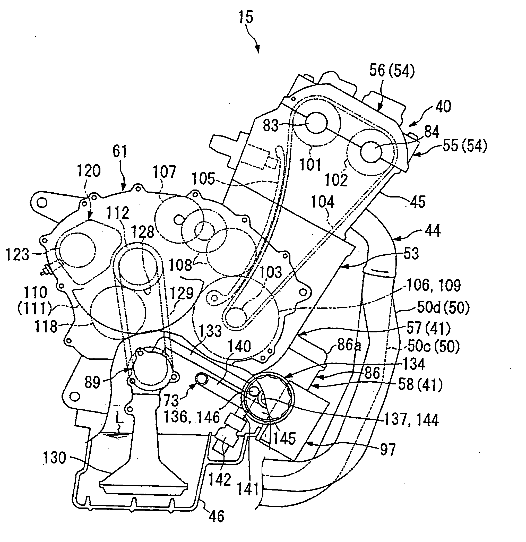
Engine crankcase structure
- Summary
- Abstract
- Description
- Claims
- Application Information
AI Technical Summary
Benefits of technology
Problems solved by technology
Method used
Image

Examples
Embodiment Construction
[0025] An embodiment of the present invention will now be described with reference to the accompanying drawings.
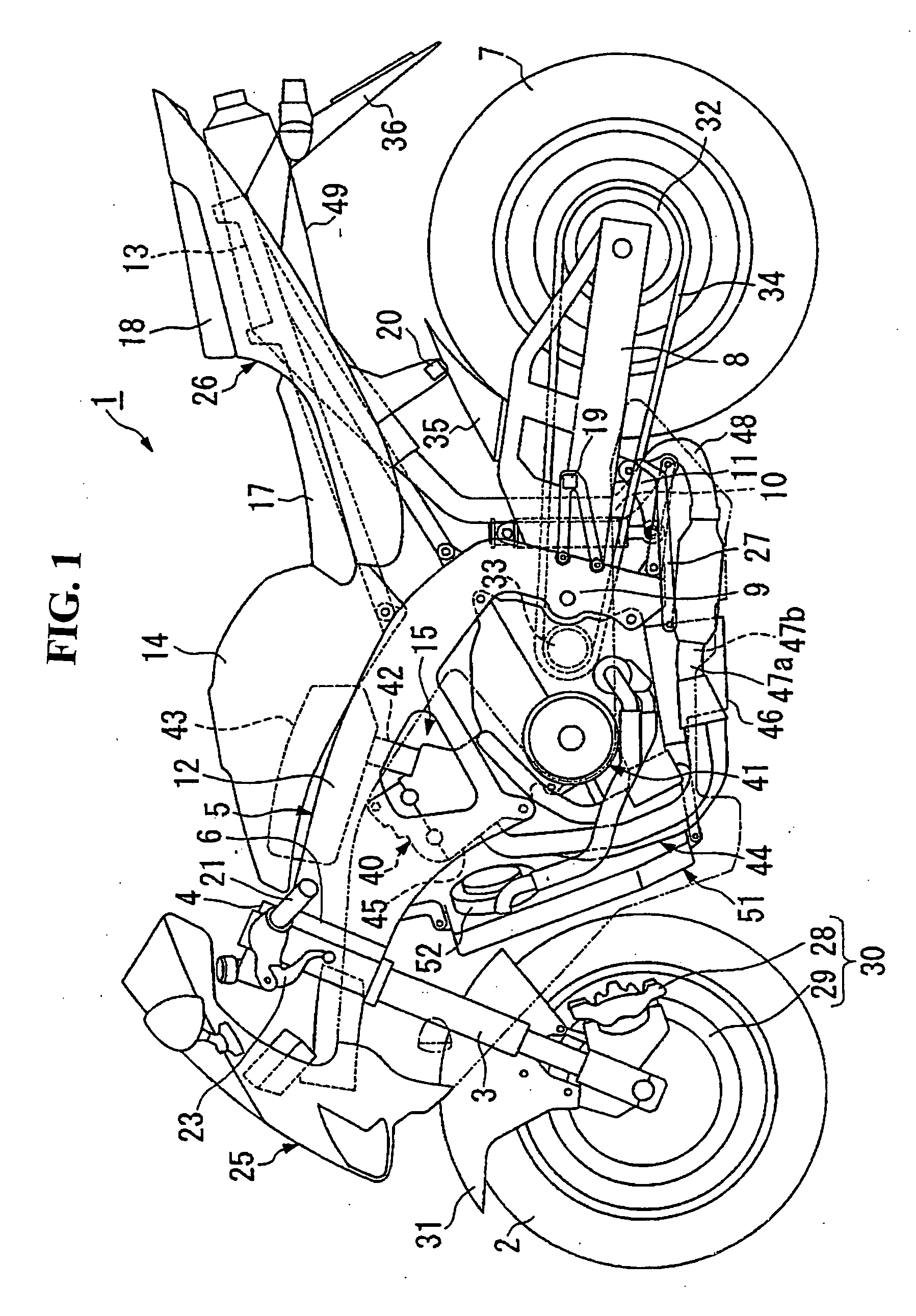
[0026] As shown in FIG. 1, a front fork 3 that supports a front wheel 2 of a motorcycle 1 is supported by a head pipe 6 provided on the front end of a body frame 5 via a steering stem 4 so that the front fork can be steered. A rear fork 8 that supports a rear wheel 7 is supported by a pivot part 9 provided on an intermediate part of the body frame 5 and the body of an engine 15 so that the rear fork can be vertically moved. The upper end of a rear cushion 10 is attached in the vicinity of the pivot part of the rear fork 8. The lower end of the rear cushion 10 is attached to a lower part of the pivot part 9 and a lower part of the body of the engine 15 via a link mechanism 11.
[0027] A main frame 12 of the body frame 5 extends backward and downward from an upper side of the head pipe 6 on the right side and on the left side. A rear end is curved downward and ranges to the ...
PUM
 Abstract
Description
Claims
Application Information
 - R&D
- Intellectual Property
- Life Sciences
- Materials
- Tech Scout
- Unparalleled Data Quality
- Higher Quality Content
- 60% Fewer Hallucinations
Browse by: Latest US Patents, China's latest patents, Technical Efficacy Thesaurus, Application Domain, Technology Topic, Popular Technical Reports.
© 2025 PatSnap. All rights reserved.Legal|Privacy policy|Modern Slavery Act Transparency Statement|Sitemap|About US| Contact US: help@patsnap.com