[0015] The FeRAM
process module must therefore be compatible with front-end process flow including the use of W contacts (currently standard in most logic flows) as the bottom contact of the capacitor. The FeRAM thermal budget must also be low enough so that it does not
impact the front-end structures such as the
low resistance structures (such as
tungsten plugs and silicided source / drains and gates) required by most logic devices. In addition, transistors and other front-end devices such as diodes are sensitive to
contamination and the FeRAM
process module cannot contaminate these devices either directly (
diffusion in
chip) or indirectly (cross contamination through shared equipment). The FeRAM devices and process module must also be compatible with a standard back end process flow. Therefore the FeRAM process module must have minimum degradation of logic metallization resistance and
parasitic capacitance between
metal and
transistor. In addition, the FeRAM devices must not be degraded by the back end process flow with minimal, if any, modification. This is a significant challenge since ferroelectric capacitors have been shown to be sensitive to
hydrogen degradation and most logic back end process flows use hydrogen /
deuterium in many of the processes (SiO2, Si3N4, and CVD W deposition, SiO2 via etch, and
forming gas anneals).
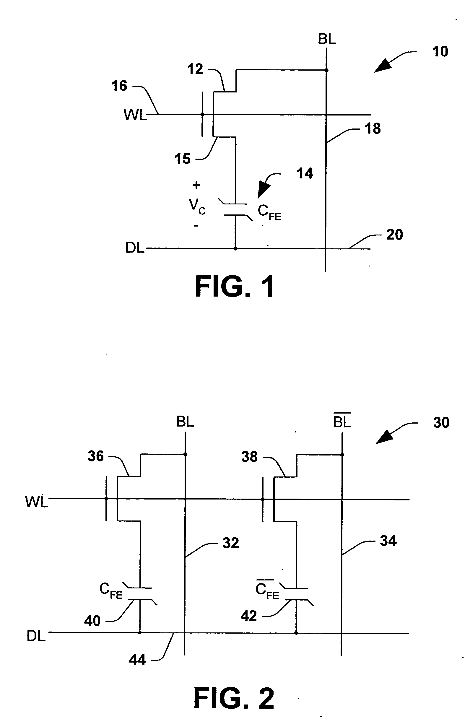
[0016] Commercial success of FeRAM also requires minimization of
embedded memory cost. Total memory cost is primarily dependent on
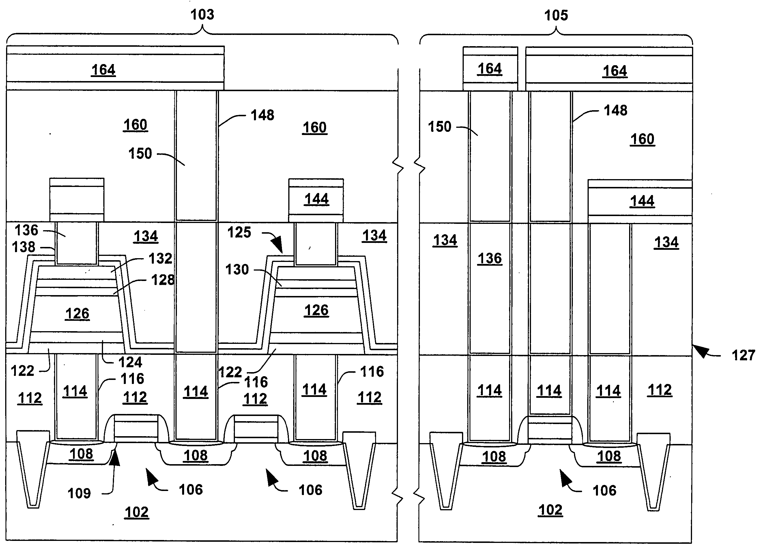
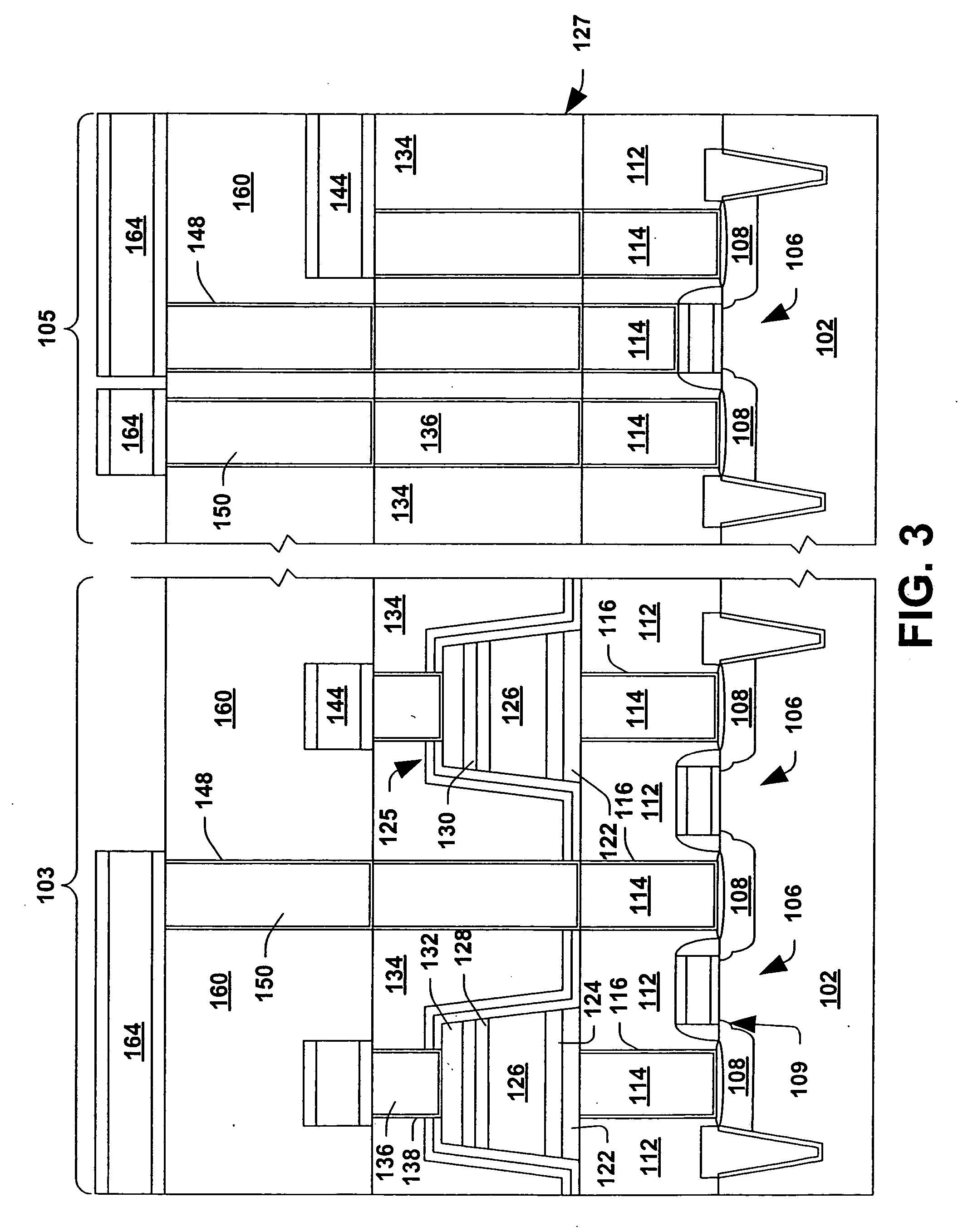
cell size, periphery ratio size,
impact of yield, and additional process costs associated with memory. In order to have a cost
advantage per bit compared to standard embedded memories such as embedded
DRAM and Flash it is necessary to have
cell sizes that are not much larger than these competing technologies. Some of the methods discussed in this patent to minimize
cell size is to make the process flow less sensitive to
lithography misalignment, have the capacitor directly over the contact, and using a single
mask for the capacitor stack etch.
[0017] In accordance with one aspect of the present invention, a method of forming an FeRAM capacitor is provided in which the
etching of the
ferroelectric capacitor stack is greatly improved. The method comprises an etch of the capacitor stack using a patterning
hard mask, for example, a TiAlN
hard mask. An etch of the PZT ferroelectric layer during the capacitor stack etch comprises a BCl3 etch at a substantially high temperature, for example, about 150° C. or more (e.g., 350° C.). Surprisingly, the BCl3 PZT etch at a relatively high temperature is substantially selective with respect to the overlying patterned hard
mask, thereby providing a quality etched PZT film without substantial hard
mask erosion, thereby resulting in good
critical dimension control of the capacitor stack.
[0018] In accordance with another aspect of the present invention, the capacitor stack comprises
iridium top and bottom
electrode layers, and a PZT ferroelectric layer disposed between the top and bottom
electrode layers. A
nitride hard mask, for example, TiAlN, is formed and patterned over the capacitor stack
layers. A Cl2+O2 or a Cl2+CO etch is employed to pattern the top electrode layer, wherein the
oxygen content therein helps provide a substantial etch selectivity with respect to the hard mask. The PZT layer is then etched with a BCl3 etch at a temperature of at least about 150° C. Unexpectedly, the high temperature BCl3 etch provides good selectivity with respect to the hard mask despite the fact that no
oxygen is provided during such etch, thereby providing for a high quality etched PZT film without substantial
erosion of the hard mask. Accordingly, a minimal capacitor stack
critical dimension is maintained. The bottom electrode is then etched in a manner similar to that of the top electrode layer.
[0019] In accordance with another aspect of the present invention, a capacitor stack etch is disclosed in which a sidewall profile of the PZT ferroelectric layer is made non-vertical. Use of a sloped or non-vertical PZT sidewall profile is not obvious because typically vertical or closely vertical sidewalls are desired to minimize the
critical dimension of the capacitor. The PZT sidewall profile is made non-vertical (e.g., less than about 88 degrees) in order to facilitate
ion impingement thereon during the subsequent etch of the bottom electrode layer. The
ion impingement (e.g.,
chlorine ions) on the sloped PZT sidewall during the bottom electrode layer etch ensures that re-deposition of conductive bottom
electrode material onto the PZT sidewall does not occur by having the removal rate thereof be greater than the
deposition rate due to re-
sputtering. Accordingly, after the bottom electrode etch, no bottom
electrode material resides on the PZT sloped sidewall, thereby preventing leakage or a shorting out of the FeRAM capacitor.
[0020] In accordance with still another aspect of the present invention, a capacitor stack etch having a sloped PZT sidewall profile comprises
etching the PZT layer with a
fluorine+Cl2+oxidizer etch
chemistry at a low temperature, for example, about 60° C. The low temperature causes the sidewall profile of the PZT to not be vertical (a non-anisotropic etch). In addition, the low PZT etch temperature surprisingly eliminates gaps or voids in the PZT ferroelectric layer that occurred with
fluorine containing etch chemistries at high temperatures. In one particular example, the PZT etch comprises a CHF3+Cl2+O2+N2 at a temperature of about 60° C., resulting in a PZT sidewall profile of less than about 88 degrees. A PZT sidewall angle of less than 88 degrees is sufficient to ensure no net deposition of conductive material thereon during the subsequent patterning of the underlying bottom electrode layer.
