Resin intake manifold for multicylinder engine
a multi-cylinder engine and intake manifold technology, applied in the direction of air intakes for fuel, combustion-air/fuel-air treatment, machines/engines, etc., can solve the problems of mass productivity, difficulty in maintaining a satisfactory welding strength, etc., to improve the rigidity of the throttle body mounting part, increase rigidity, and firm intake manifold
- Summary
- Abstract
- Description
- Claims
- Application Information
AI Technical Summary
Benefits of technology
Problems solved by technology
Method used
Image

Examples
embodiment 1
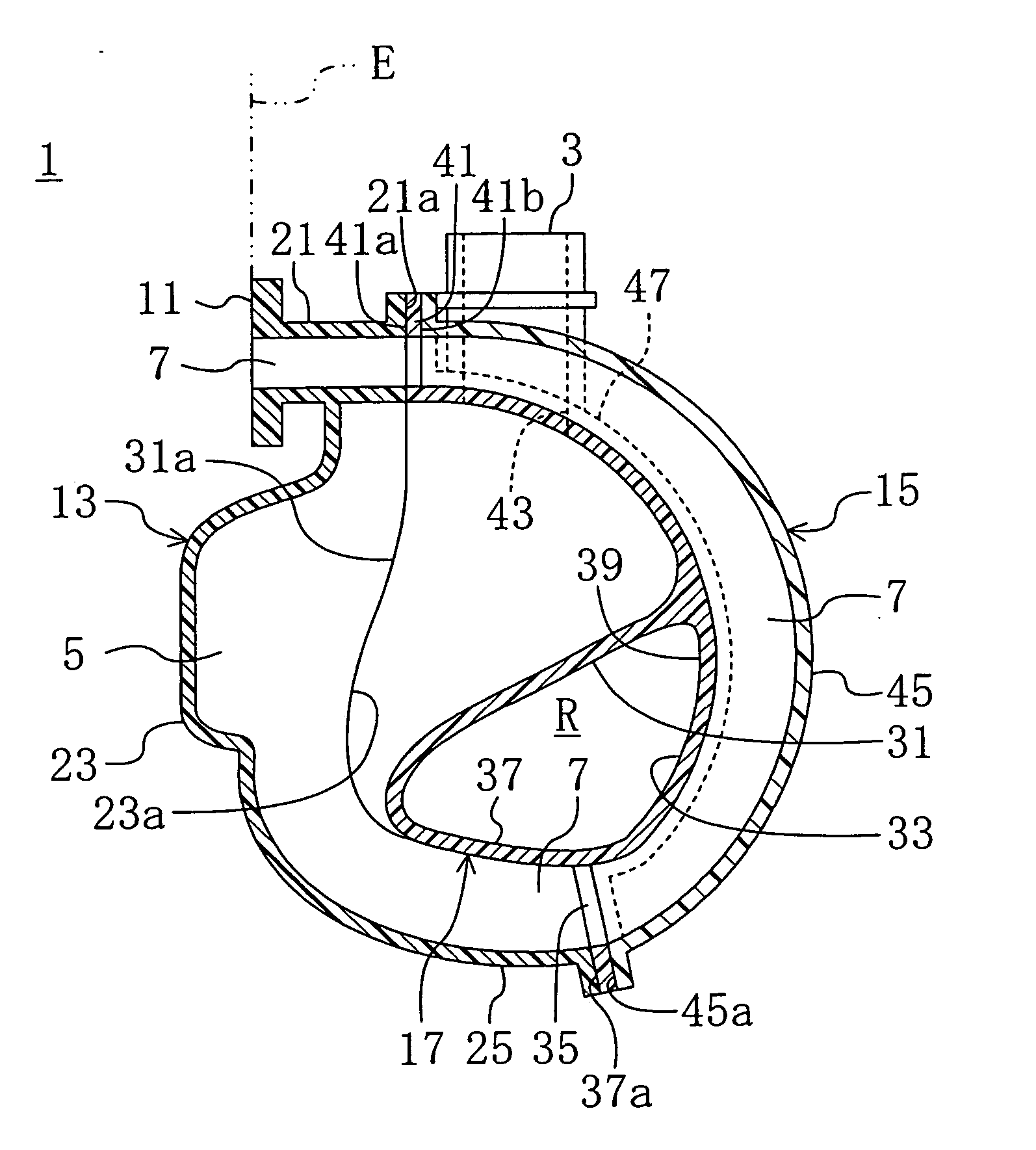
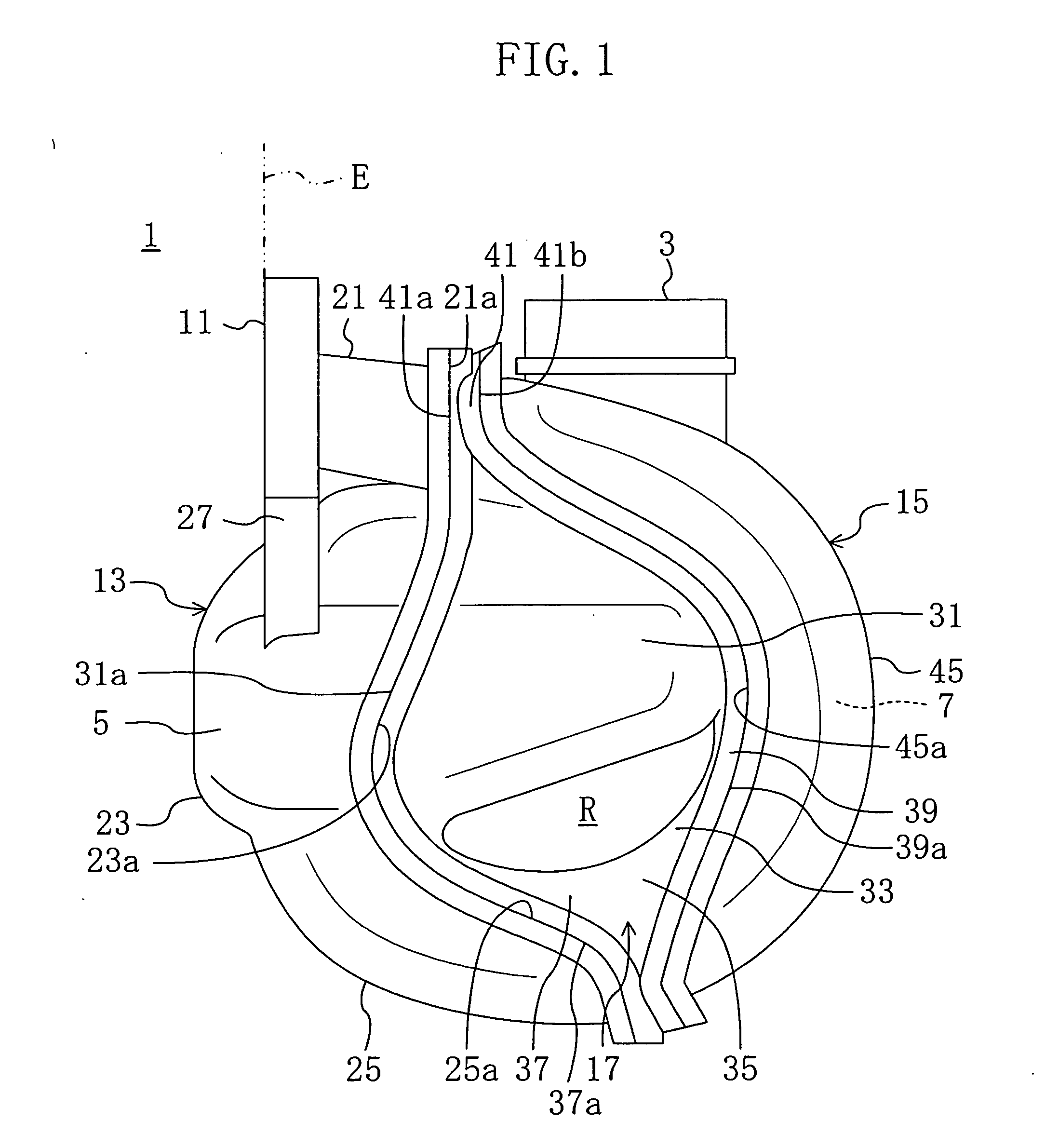
[0026]FIG. 1 shows a resin intake manifold 1 for a multicylinder engine according to Embodiment 1 of the present invention. The intake manifold 1 is mounted on an inline four-cylinder engine E including four cylinders connected in line. The intake manifold 1 is made of a resin and includes integral parts of: a cylindrical throttle body mounting part 3 to which a throttle body (not shown) having a throttle valve is attached; a surge tank 5 which communicates with the inside of the throttle body mounting part 3; and four individual intake paths 7 which communicate with the surge tank 5 and intake ports (not shown) of the cylinders.
[0027] The surge tank 5 is located substantially at the vertical center of the intake manifold 1. The throttle body mounting part 3 is provided at the top of the surge tank 5. The four intake paths 7 are aligned in the direction of the arrangement of the cylinders of the engine E. As seen in FIG. 5, the upstream ends of the intake paths 7 are connected to t...
embodiment 2
[0050]FIG. 7 is a view illustrating a resin intake manifold 1 for a multicylinder engine according to Embodiment 2 of the present invention. The intake manifold 1 of Embodiment 2 is different from that of Embodiment 1 in that the throttle body mounting part 3 is integrally formed with the middle manifold component 17. In the following explanation, the same components as those of Embodiment 1 are given with the same reference numerals used in Embodiment 1 and only the difference from Embodiment 1 is explained in detail.
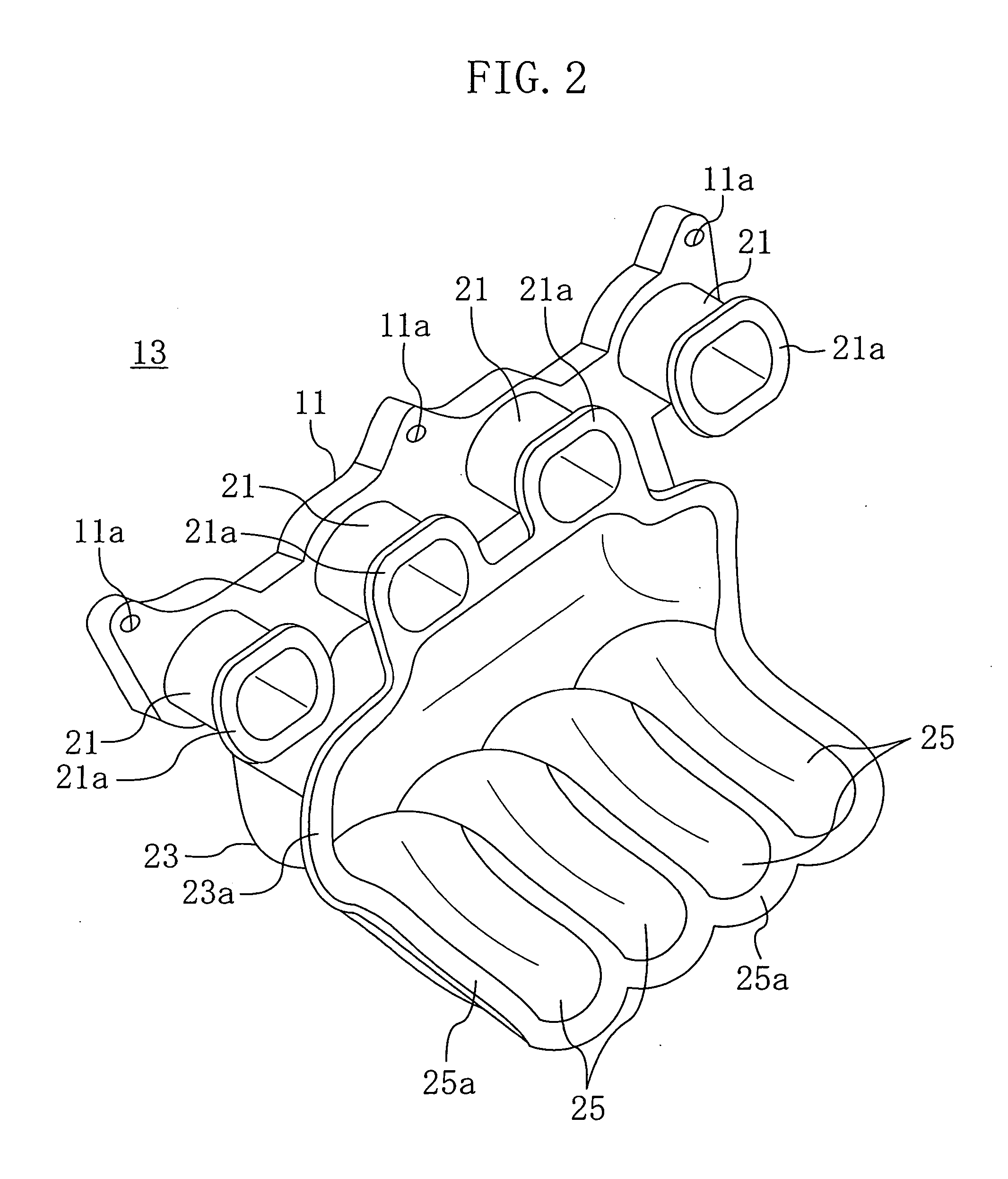
[0051] The near manifold component 13 has first path-forming parts 25 which are shorter than those of the near manifold component 13 of Embodiment 1. The second path-forming parts 37 of the middle manifold component 17 are joined on and vibration-welded to the first path-forming parts 25.
[0052] Four cylindrical parts 61 are integrally formed at the upper part of the middle manifold component 17 to constitute the downstream sides of the intake paths 7. The cylindrical...
PUM
| Property | Measurement | Unit |
|---|---|---|
| cylindrical shape | aaaaa | aaaaa |
| degree of freedom | aaaaa | aaaaa |
| weight | aaaaa | aaaaa |
Abstract
Description
Claims
Application Information
 - R&D
- Intellectual Property
- Life Sciences
- Materials
- Tech Scout
- Unparalleled Data Quality
- Higher Quality Content
- 60% Fewer Hallucinations
Browse by: Latest US Patents, China's latest patents, Technical Efficacy Thesaurus, Application Domain, Technology Topic, Popular Technical Reports.
© 2025 PatSnap. All rights reserved.Legal|Privacy policy|Modern Slavery Act Transparency Statement|Sitemap|About US| Contact US: help@patsnap.com