Connector
- Summary
- Abstract
- Description
- Claims
- Application Information
AI Technical Summary
Benefits of technology
Problems solved by technology
Method used
Image

Examples
Embodiment Construction
[0042] A preferred embodiment of a connector of the present invention will now be described with reference to the drawings.
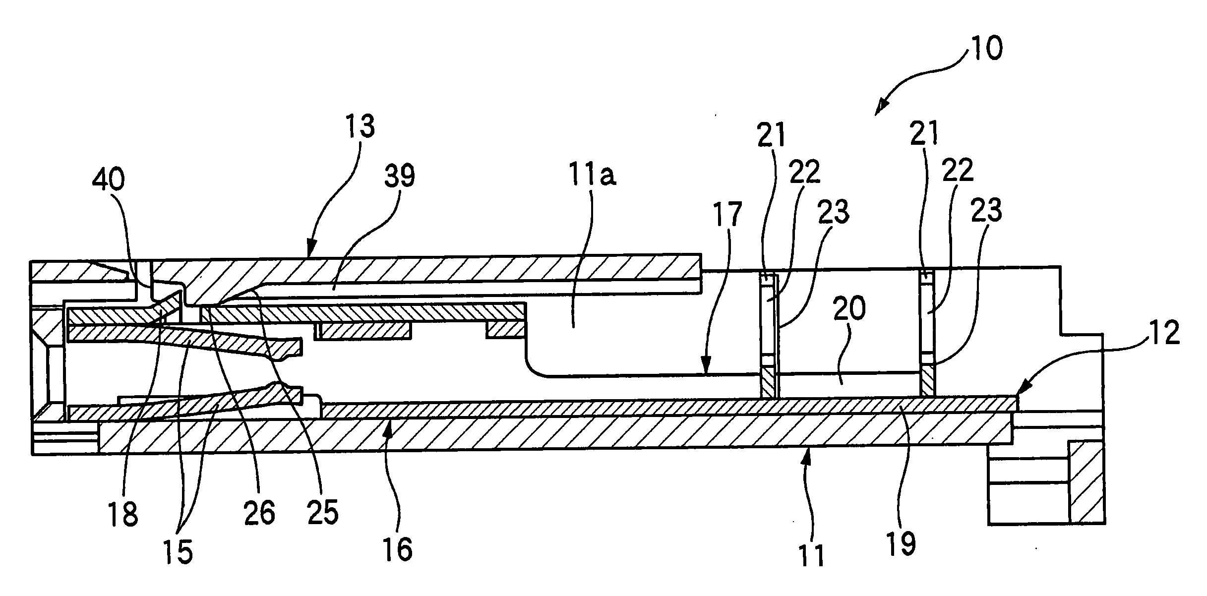
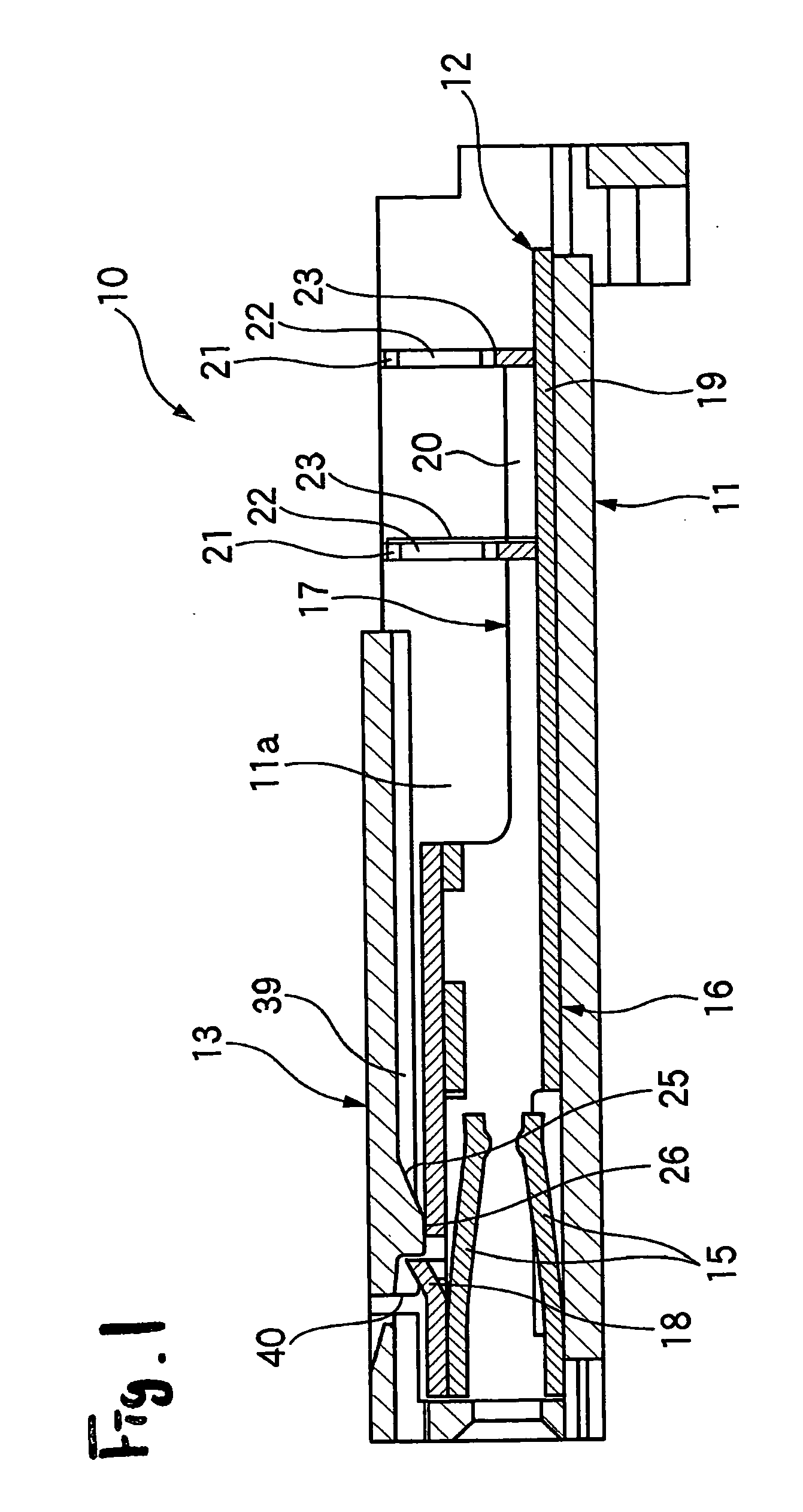
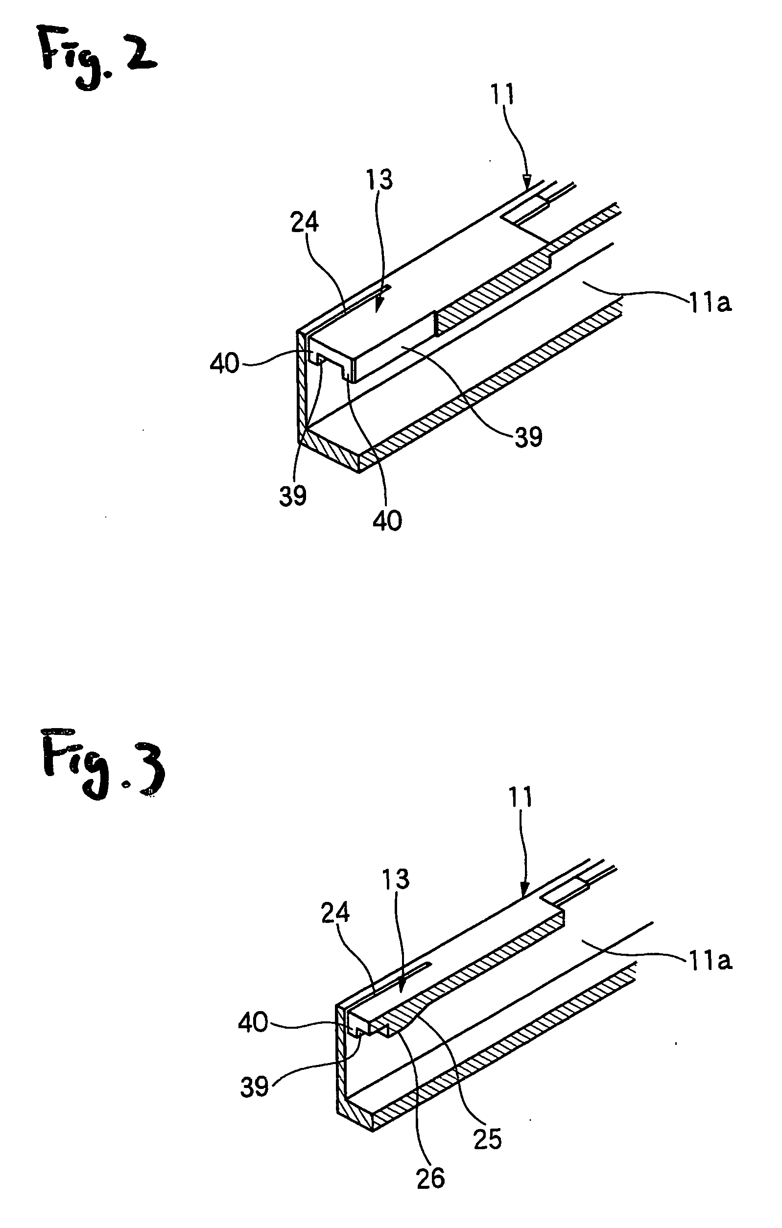
[0043]FIG. 1 is a cross-sectional view explanatory of one preferred embodiment of the connector of the invention, FIG. 2 is a partly-broken, perspective view of a connector housing of the connector of FIG. 1, showing an elastic retaining piece portion of the connector, and FIG. 3 is a perspective view, showing a condition in which the elastic retaining piece portion of FIG. 2 is broken along a direction of withdrawing of a terminal.
[0044] As shown in FIG. 1, the connector 10 of this embodiment includes the synthetic resin-made connector housing 11 having a terminal receiving chamber 11a, and the terminal 12 (which is formed by pressing an electrically-conductive metal sheet) is inserted into the terminal receiving chamber 11a through a rear opening thereof. The retaining lance (elastic retaining piece portion) 13 for retaining the terminal 12 received in the t...
PUM
 Abstract
Description
Claims
Application Information
 - R&D
- Intellectual Property
- Life Sciences
- Materials
- Tech Scout
- Unparalleled Data Quality
- Higher Quality Content
- 60% Fewer Hallucinations
Browse by: Latest US Patents, China's latest patents, Technical Efficacy Thesaurus, Application Domain, Technology Topic, Popular Technical Reports.
© 2025 PatSnap. All rights reserved.Legal|Privacy policy|Modern Slavery Act Transparency Statement|Sitemap|About US| Contact US: help@patsnap.com