Method of induction weld forming with shear displacement step
- Summary
- Abstract
- Description
- Claims
- Application Information
AI Technical Summary
Benefits of technology
Problems solved by technology
Method used
Image

Examples
Embodiment Construction
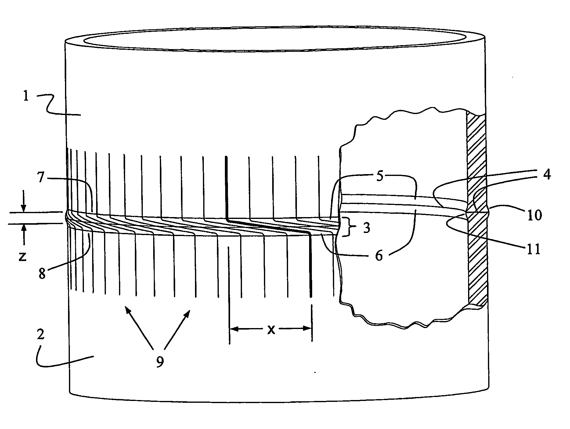
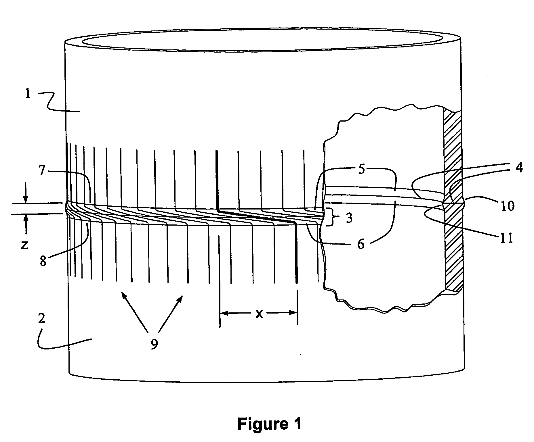
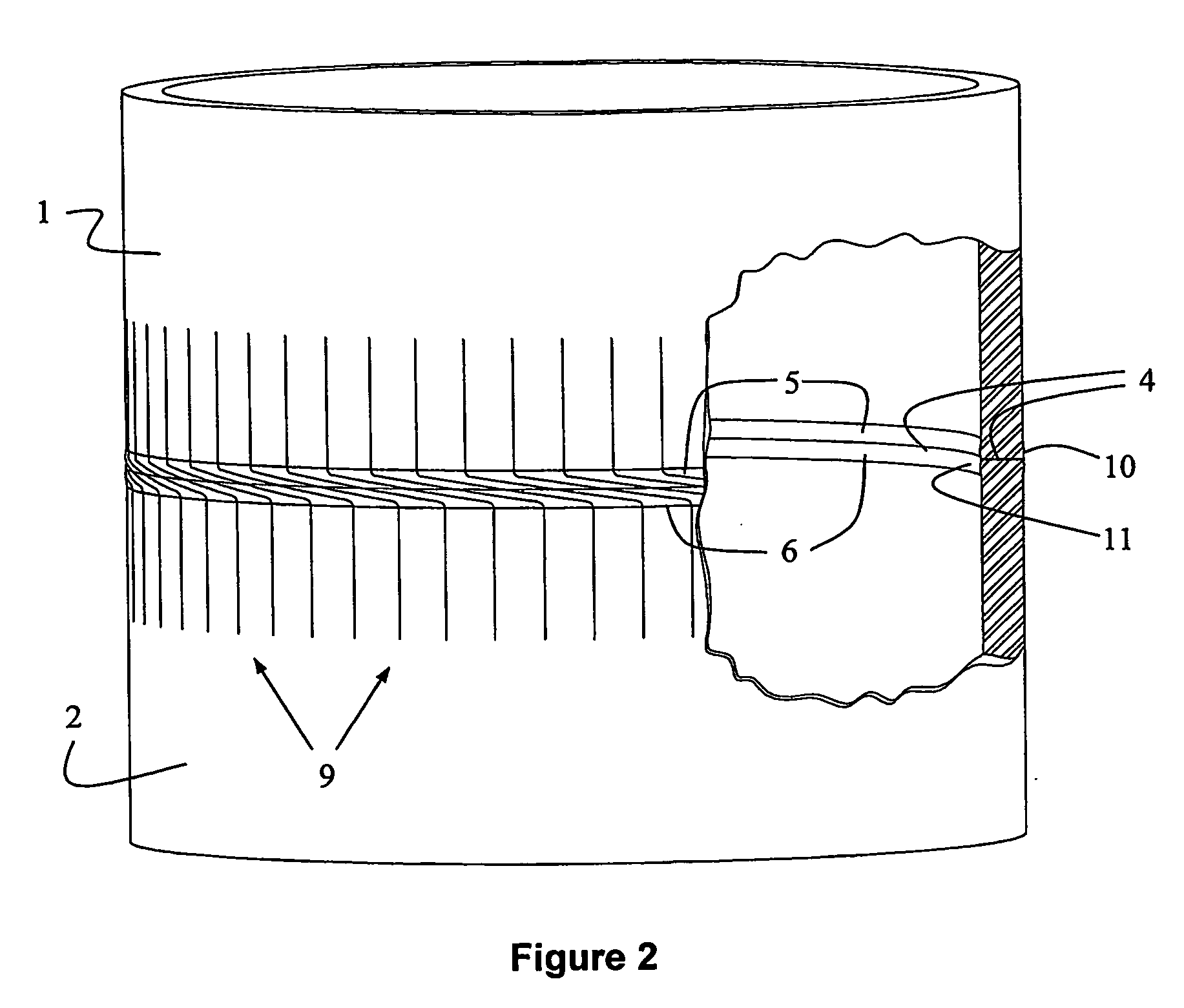
[0071]FIG. 1 illustrates a shear-assisted solid state weld formed by the preferred method of the present invention as it appears in a welded tube or pipe. In FIG. 1, a first metal tubular work piece 1 is coaxially welded to a second metal tubular work piece 2 to create a weld zone 3. The weld zone 3 is bisected by a bond line 4 and is generally defined by first and second heat affected zones, 5 and 6, on the welded ends 7 and 8 of the first and second work pieces respectively.
[0072] According to the preferred method of the present invention, the shearing required to activate the bond in weld zone 3, as described above, is input as uni-directional coaxial relative rotation between work pieces 1 and 2. In such case, axial reference lines scribed along the work pieces 1 and 2, prior to welding, would be distorted and appear as curved lines 9 after welding, which lines show the plastic shear distortion imposed by the welding process. It will be apparent that where line slope is steepes...
PUM
| Property | Measurement | Unit |
|---|---|---|
| Thickness | aaaaa | aaaaa |
| Thickness | aaaaa | aaaaa |
| Thickness | aaaaa | aaaaa |
Abstract
Description
Claims
Application Information
 - R&D
- Intellectual Property
- Life Sciences
- Materials
- Tech Scout
- Unparalleled Data Quality
- Higher Quality Content
- 60% Fewer Hallucinations
Browse by: Latest US Patents, China's latest patents, Technical Efficacy Thesaurus, Application Domain, Technology Topic, Popular Technical Reports.
© 2025 PatSnap. All rights reserved.Legal|Privacy policy|Modern Slavery Act Transparency Statement|Sitemap|About US| Contact US: help@patsnap.com