Mobile transceiver and antenna device
a transceiver and antenna technology, applied in the direction of antennas, antenna details, antenna earthings, etc., can solve the problems of defective built-in antennas, difficult to realize omnidirectional radiation patterns, and difficult to pass electric waves through circuit boards, etc., to improve the gain of the surface opposite
- Summary
- Abstract
- Description
- Claims
- Application Information
AI Technical Summary
Benefits of technology
Problems solved by technology
Method used
Image

Examples
first embodiment
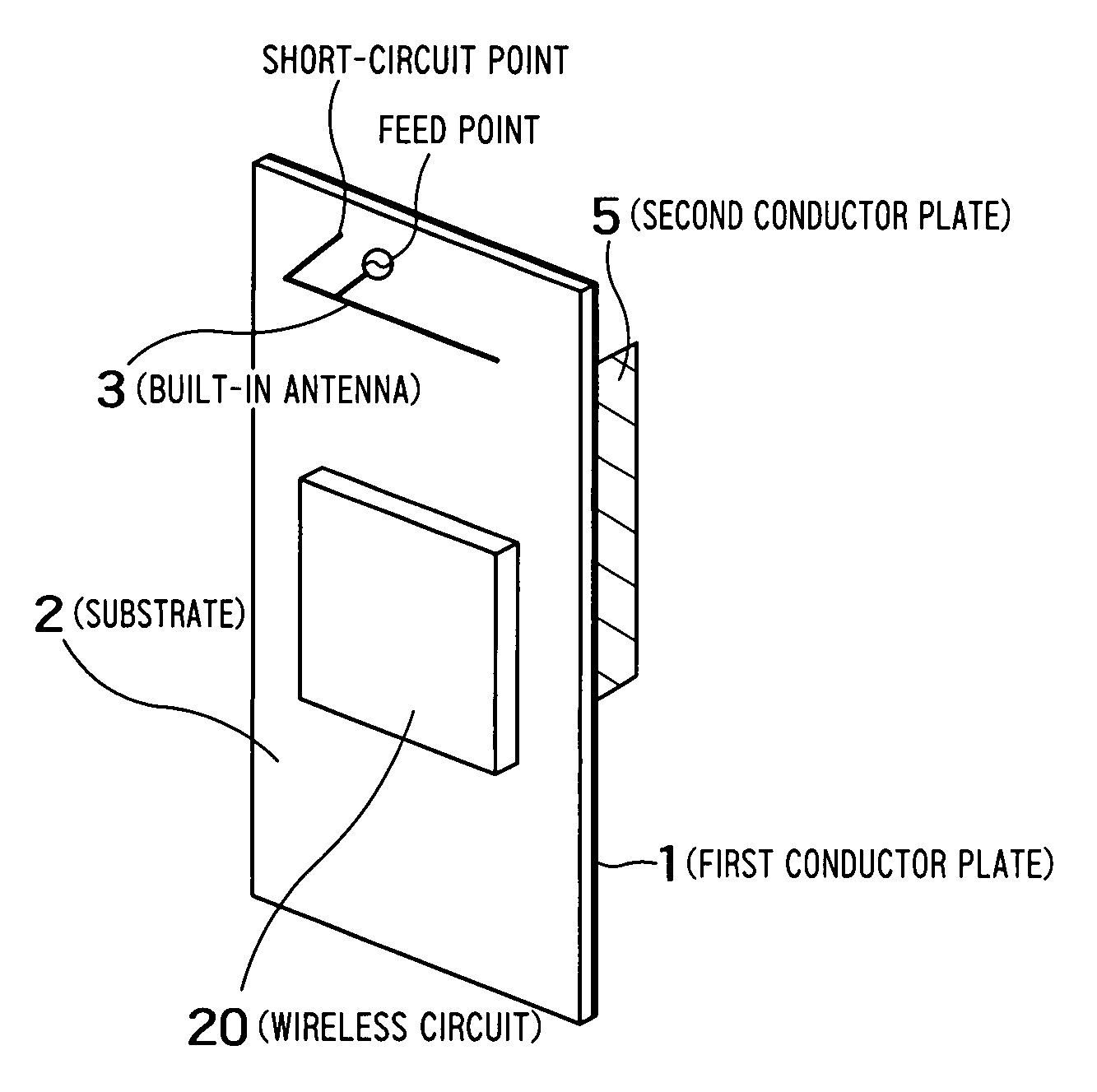
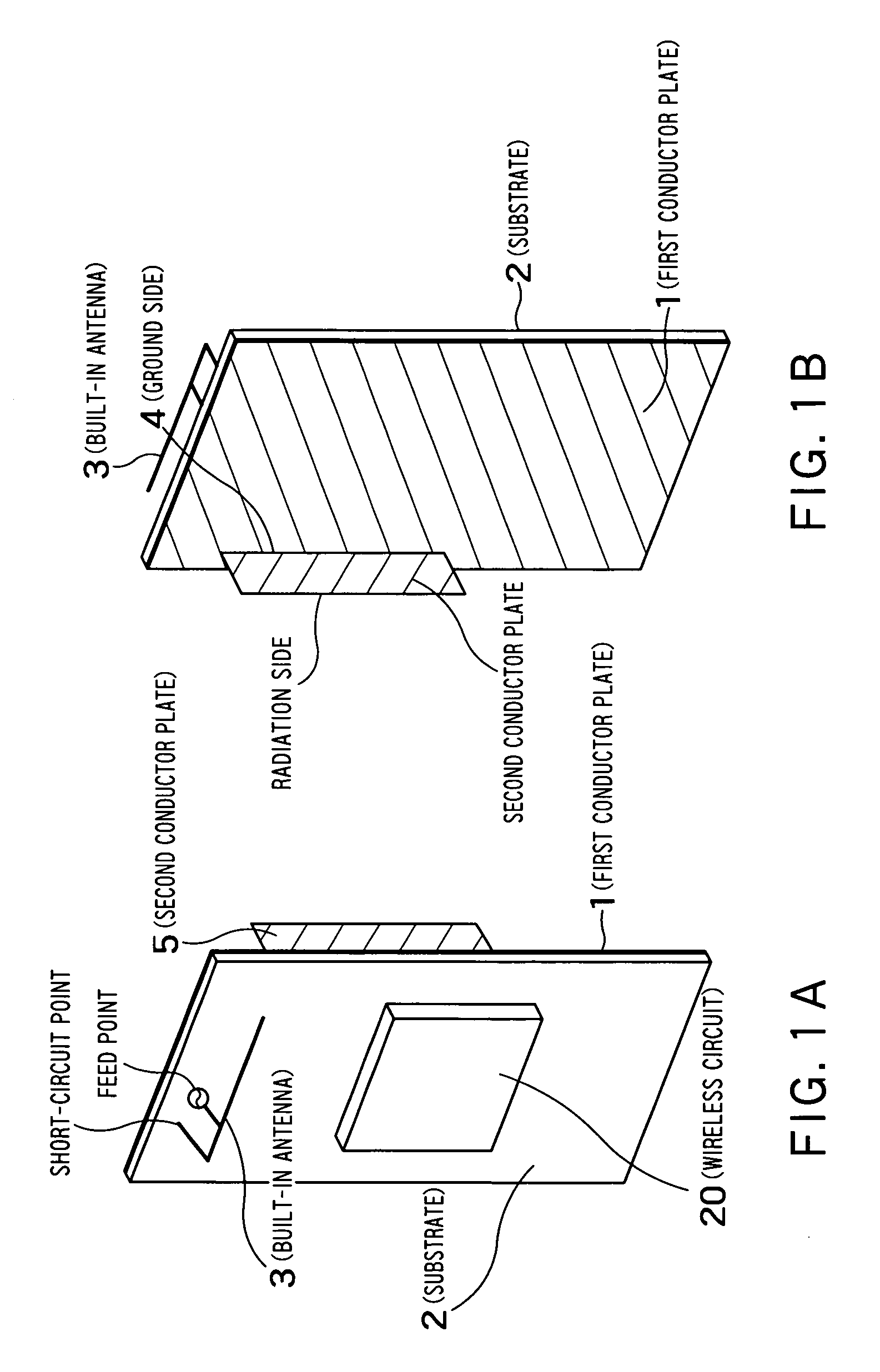
[0041]FIGS. 1A and 1B are views showing an arrangement of an antenna device built in a transceiver according to a first embodiment of the present invention. The antenna device has a feature in that it includes a substrate 2 having two surfaces, a built-in antenna 3 disposed on one of the surfaces of the substrate 2, a first conductor plate 1 disposed on the other surface of the substrate 2 on which the built-in antenna 3 is not disposed, and a second conductor plate 5 connected to the first conductor plate 1. A wireless circuit 20 is mounted on the substrate 2 to realize a wireless communication function. FIG. 1A is a perspective view when the antenna device is viewed from the direction of the substrate 2, and FIG. 1B is a perspective view when the antenna device is viewed from the first conductor plate 1 side. With the above arrangement, a gain in a direction opposite to the surface on which the built-in antenna 3 is disposed is improved, thereby a radiation pattern near to omnidir...
second embodiment
[0085]FIG. 27 is a configurational view of an antenna device built in a mobile transceiver according to a second embodiment. The embodiment includes a substrate 2 having a first conductor plate 1, a built-in antenna 3 disposed on one surface of the first conductor plate 1 and having a feed point on the surface, and a plurality of second conductor plates 5 disposed on the other surface of the first conductor plate 1, which is different from the one surface on which the built-in antenna 3 is disposed, and having ground sides 4 grounded to the first conductor plate 1. The second conductor plates 5 are disposed at intervals of λ / 2. With this arrangement, a gain in a direction opposite to the surface, on which the built-in antenna 3 is disposed, is improved, thereby a radiation pattern near to omnidirectionality can be realized. Since the same components as those of the first embodiment are employed in the second embodiment, explanation thereof is omitted.
[0086] The embodiment has a fea...
third embodiment
[0089]FIG. 28 is a configurational view of an antenna device built in a mobile transceiver according to a third embodiment. The antenna device is composed of a substrate 2 having a first conductor plate 1, a built-in antenna 3 disposed on one surface of the first conductor plate 1 and having a feed point on the surface, and a second conductor plate 5 disposed on the other surface of the first conductor plate 1, which is different from the one surface on which the built-in antenna 3 is disposed, and grounded to the first conductor plate 1 at a plurality of positions. The antenna device has a feature in that the portion thereof other than the outer peripheral portion of the second conductor plate 5 is composed of a dielectric material, and an integrated circuit 14 is mounted on the dielectric material.
[0090] The portion of the second conductor plate 5 other than the outer peripheral portion less contributes to radiation. Thus, in the embodiment, the portion of the second conductor pl...
PUM
 Abstract
Description
Claims
Application Information
 - R&D
- Intellectual Property
- Life Sciences
- Materials
- Tech Scout
- Unparalleled Data Quality
- Higher Quality Content
- 60% Fewer Hallucinations
Browse by: Latest US Patents, China's latest patents, Technical Efficacy Thesaurus, Application Domain, Technology Topic, Popular Technical Reports.
© 2025 PatSnap. All rights reserved.Legal|Privacy policy|Modern Slavery Act Transparency Statement|Sitemap|About US| Contact US: help@patsnap.com