Force Generator
a generator and force technology, applied in the direction of generator/motor, mechanical vibration separation, shock absorber, etc., can solve the problems of small acceleration, large coil mass, small force generation, etc., and achieve large acceleration, large vibration amplitude, and large force
- Summary
- Abstract
- Description
- Claims
- Application Information
AI Technical Summary
Benefits of technology
Problems solved by technology
Method used
Image

Examples
first embodiment
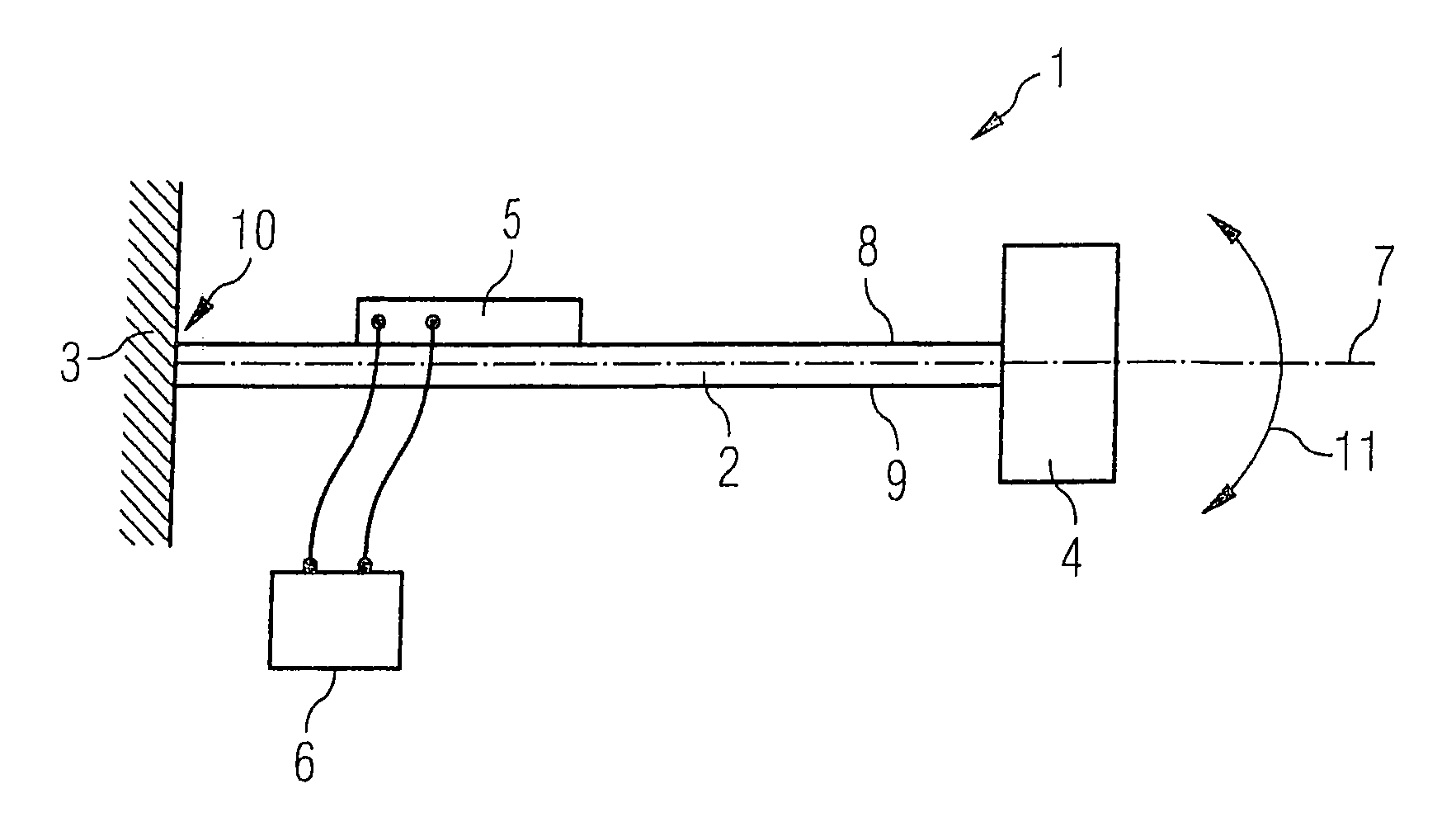
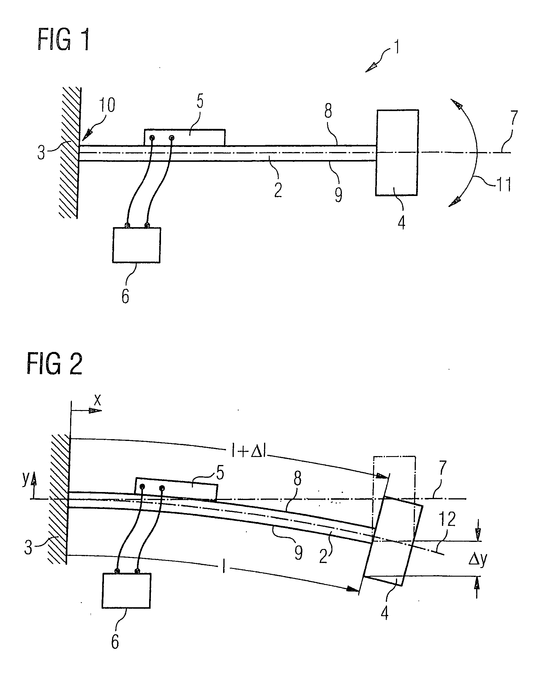
[0038]FIG. 1 schematically depicts force generator 1 according to the present invention. It comprises a flexural arm 2 that is attached at one end 10 to a structure 3, and comprises an inertial mass 4 at the other end. Structure 3 is, for example, an aircraft, a motor vehicle, a machine component, or any other component; structure 3 vibrates in an undesired fashion. To reduce these vibrations, force generator 1 is connected to structure 3 so that counter-vibrations can be deliberately introduced into structure 3 in order to reduce the overall level of the vibrations in structure 3, as explained below in greater detail.
[0039]Mounted on flexural arm 2 is an electromagnetic transducer 5, in particular a piezoelectric actuator, that is electrically connected to a driving system 6. The position of driving system 6 is arranged at a distance from flexural arm 2 and from transducer 5 such that it does not impede the movement of flexural arm 2 including transducer 5 and inertial mass 4. In t...
second embodiment
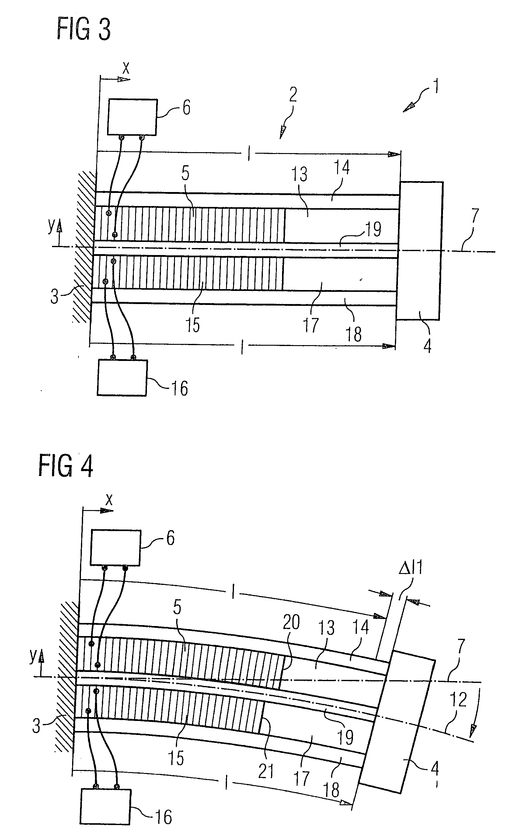
[0044]FIG. 3 depicts the force generator according to the invention. Flexural arm 2 is constructed in a layered design. It has a neutral ply 19 that extends along center line 7 of flexural arm 2. Parallel thereto, flexural arm 2 has an upper outer ply 14 and a lower outer ply 18. Arranged between upper outer ply 14 and neutral ply 19 are a first actuator constituting electromagnetic transducer 5, and an additional element 13 that is hereinafter also referred to as a spacing element, which occupies the distance between actuator 5 and inertial mass 4 as well as the distance between neutral ply 19 and upper outer ply 14. A second actuator 15, and a spacing element 17 adjoining it, are located in the same fashion between neutral ply 19 and lower outer ply 18. First actuator 5 is coupled to a driving system 6, and second actuator 15 to a driving system 16, which systems are respectively regulated as a function of sensor signals that are received from corresponding sensors for sensing the...
PUM
 Abstract
Description
Claims
Application Information
 - R&D
- Intellectual Property
- Life Sciences
- Materials
- Tech Scout
- Unparalleled Data Quality
- Higher Quality Content
- 60% Fewer Hallucinations
Browse by: Latest US Patents, China's latest patents, Technical Efficacy Thesaurus, Application Domain, Technology Topic, Popular Technical Reports.
© 2025 PatSnap. All rights reserved.Legal|Privacy policy|Modern Slavery Act Transparency Statement|Sitemap|About US| Contact US: help@patsnap.com