Electronic equipment system
- Summary
- Abstract
- Description
- Claims
- Application Information
AI Technical Summary
Benefits of technology
Problems solved by technology
Method used
Image

Examples
embodiment 1
[0036]A first embodiment of the present invention will be shown in FIG. 1 and FIG. 2.
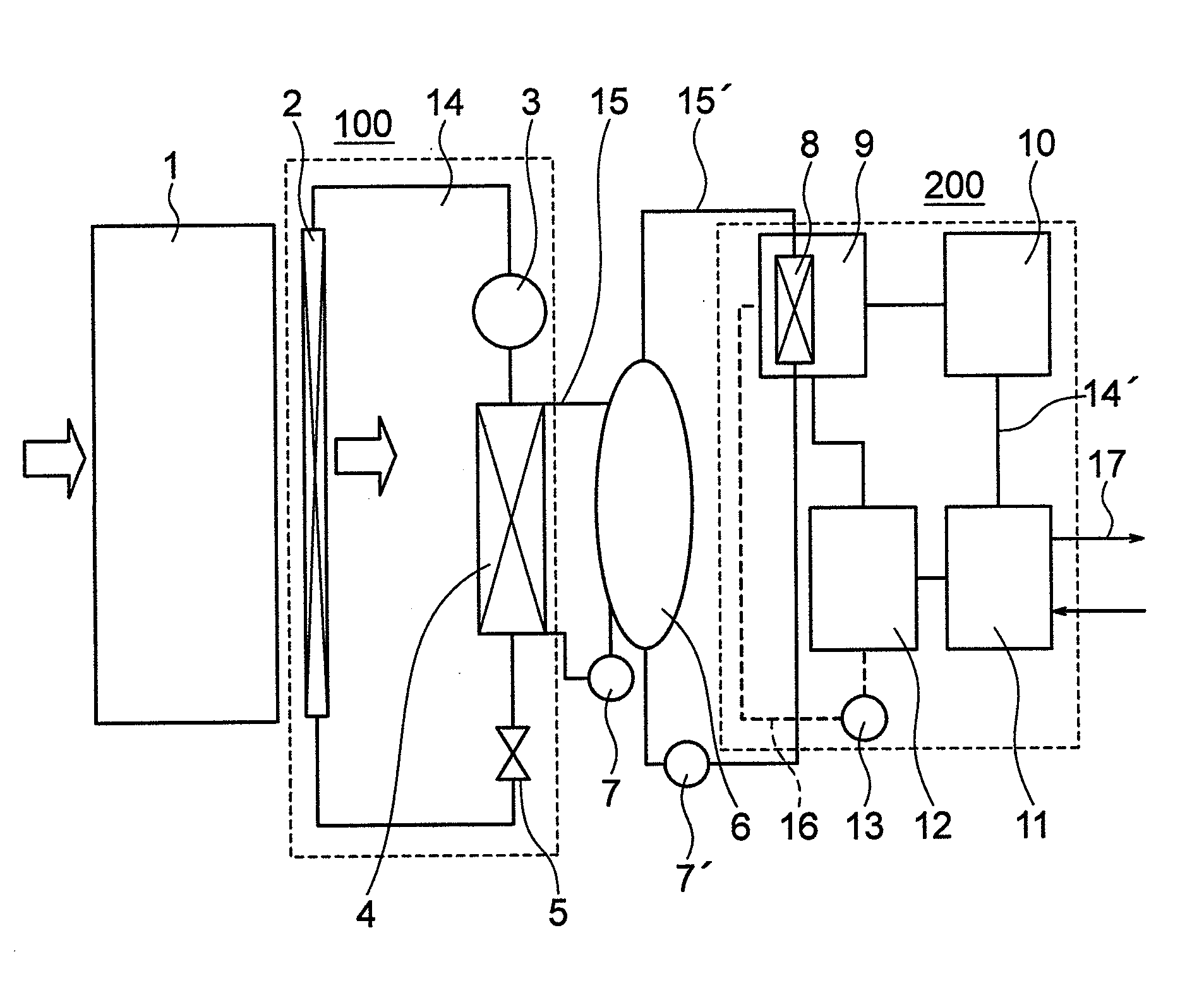
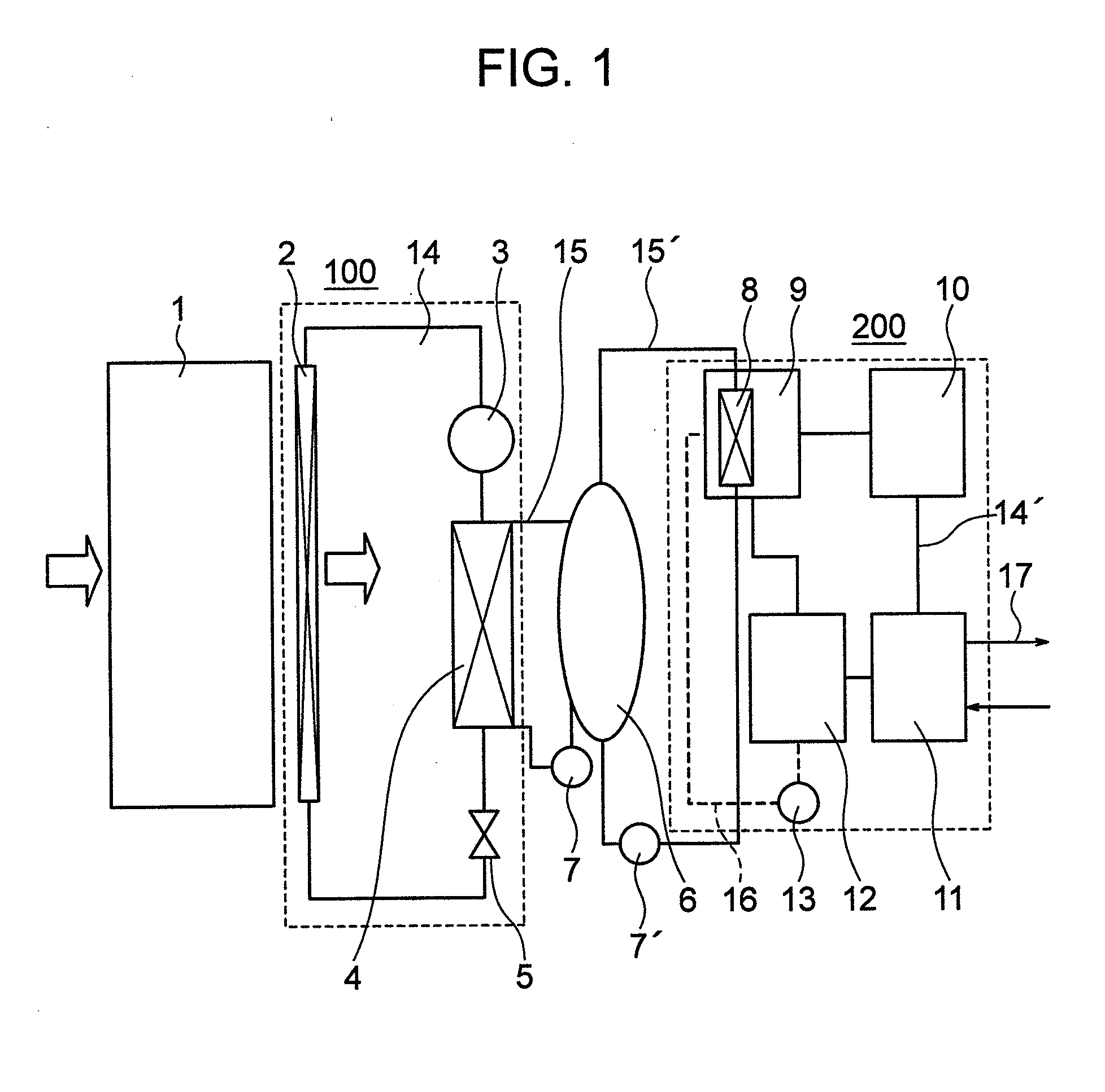
[0037]FIG. 1 is a configuration diagram of a disk array apparatus and electronic equipment system according to a first embodiment.
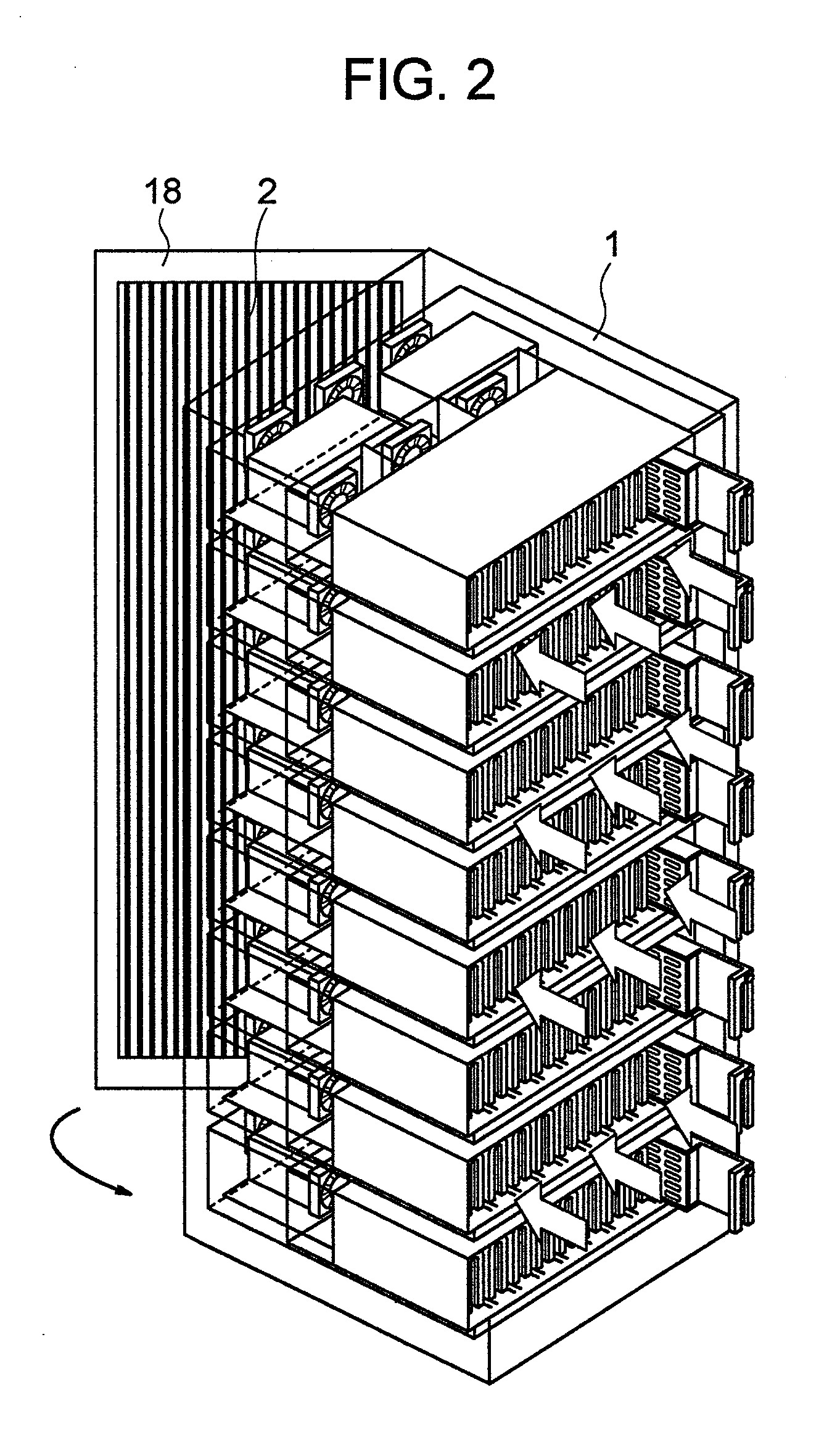
[0038]FIG. 2 is a perspective view of the disk array apparatus and electronic equipment provided with the first embodiment.
[0039]As shown in the figures, the disk array apparatus and electronic equipment system are constructed of an apparatus housing 1 which is a disk array apparatus or electronic equipment, a vapor compression cycle 100, a hot water tank 6 and an absorption cycle 200 or the like.
[0040]The vapor compression cycle 100 is constructed of an air source evaporator 2, a compressor 3, a water heat source condenser 4, an expansion valve 5 and a refrigerant line 14 which connects these components or the like. This vapor compression cycle 100 is called a “refrigeration cycle” and refers to a general, so-called refrigeration cycle which is introduced into a home roo...
embodiment 2
[0054]A second embodiment of the present invention will be shown in FIG. 3.
[0055]FIG. 3 is a configuration diagram of a disk array apparatus and electronic equipment system of this embodiment.
[0056]In FIG. 3, the disk array apparatus and electronic equipment system are constructed of an apparatus housing 1 which is the disk array apparatus or electronic equipment, a vapor compression cycle 100, a hot water tank 6 and an absorption cycle 200 or the like. The vapor compression cycle 100 is constructed of an air source evaporator 2, a compressor 3, a water heat source condenser 4, an expansion valve 5 and a refrigerant line 14 that connects these components or the like. Chlorofluorocarbon alternatives such as R410A or a natural refrigerant such as CO2 are used as a refrigerant. Furthermore, the absorption cycle 200 is constructed of a generator 9, a condenser 10, an evaporator 11, an absorber 12, a solution pump 13 and a refrigerant line 14′ and a solution line 16 that connect these co...
embodiment 3
[0064]A third embodiment of the present invention is shown in FIG. 4 and FIG. 5.
[0065]FIG. 4 is a configuration diagram of a disk array apparatus and electronic equipment system of this embodiment.
[0066]In FIG. 4, the disk array apparatus and electronic equipment system are constructed of an apparatus housing 1 which is the disk array apparatus or electronic equipment, a vapor compression cycle 100, a hot water tank 6 and an absorption cycle 200 or the like.
[0067]The vapor compression cycle 100 is constructed of an air source evaporator 2, a compressor 3, a water heat source condenser 4 and an expansion valve 5 or the like. Chlorofluorocarbon alternatives such as R410A or a natural refrigerant such as CO2 are used as a refrigerant. Furthermore, the absorption cycle 200 is constructed of a generator 9, a condenser 10, an evaporator 11, an absorber 12 and a solution pump 13 or the like. A natural refrigerant such as water is used as a refrigerant and lithium bromide or the like is use...
PUM
 Abstract
Description
Claims
Application Information
 - R&D
- Intellectual Property
- Life Sciences
- Materials
- Tech Scout
- Unparalleled Data Quality
- Higher Quality Content
- 60% Fewer Hallucinations
Browse by: Latest US Patents, China's latest patents, Technical Efficacy Thesaurus, Application Domain, Technology Topic, Popular Technical Reports.
© 2025 PatSnap. All rights reserved.Legal|Privacy policy|Modern Slavery Act Transparency Statement|Sitemap|About US| Contact US: help@patsnap.com