Device with an electromagnet, clutch, and method for producing an electromagnet
- Summary
- Abstract
- Description
- Claims
- Application Information
AI Technical Summary
Benefits of technology
Problems solved by technology
Method used
Image

Examples
Embodiment Construction
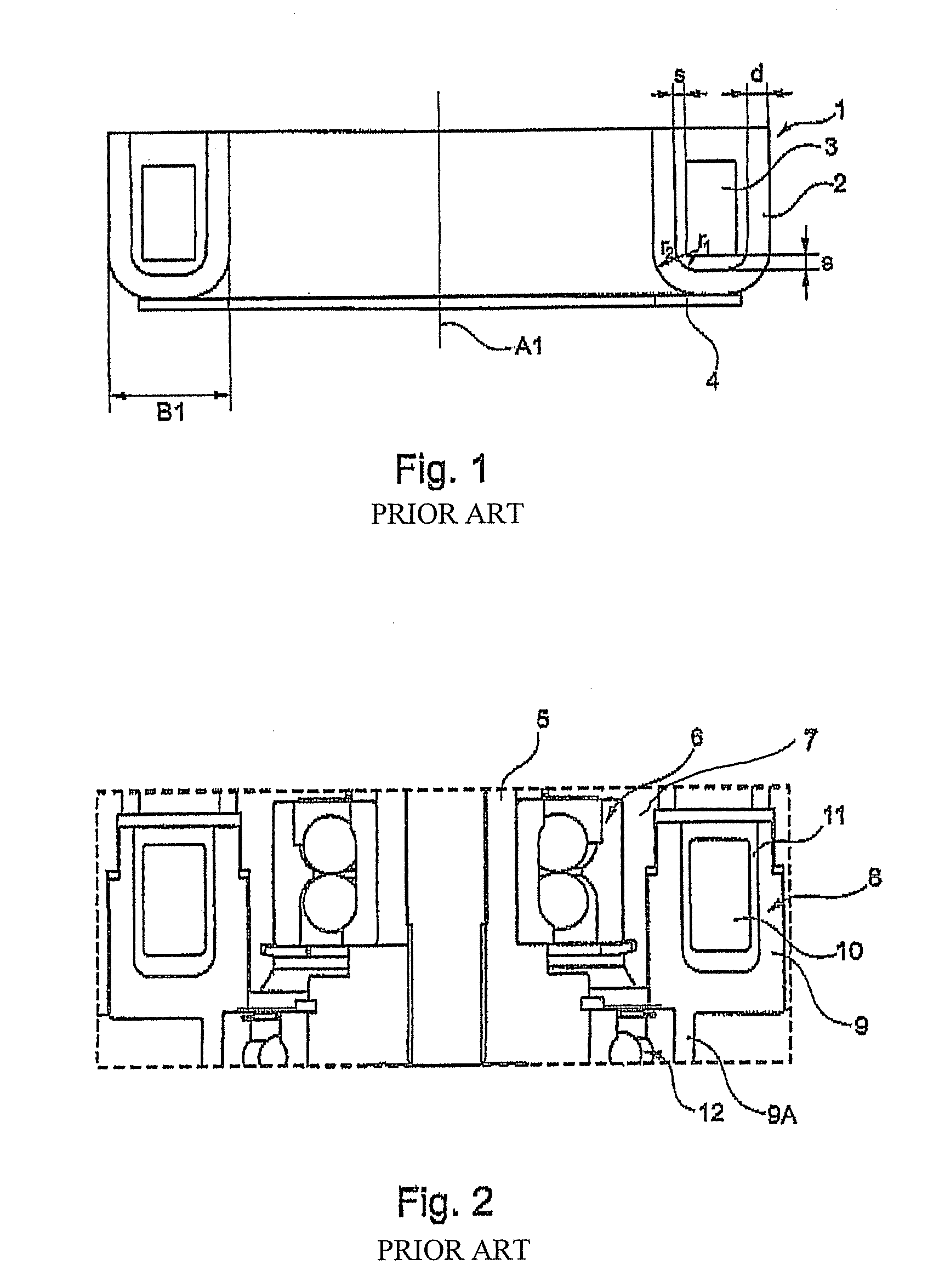
[0039]FIG. 1 shows, schematically, a section through a known annular electromagnet 1 in which, in order to simplify the illustration, individual parts and details are not illustrated. The electromagnet 1 comprises a U-shaped steel body 2 shaped from sheet-metal material. The steel body 2 is closed in an annular shape and is used to accommodate a likewise annular coil former 3, which is shown only schematically, with a rectangular cross section. In addition, FIG. 1 shows a flange ring 4 which, for example, can be used for fitting the electromagnet 1 to adjacent components. The flange ring 4 is fitted to the connecting part between the free limbs of the U-shaped steel body 2.
[0040]The sheet-metal thickness “d” of the steel body 2 composed of ferromagnetic material may, for example, be several millimeters, in this case about 5 mm, with the sheet-metal material forming a magnetic-field guide around the coil former 3. An installation area B1 is available in the radial direction, circumfe...
PUM
 Abstract
Description
Claims
Application Information
 - R&D
- Intellectual Property
- Life Sciences
- Materials
- Tech Scout
- Unparalleled Data Quality
- Higher Quality Content
- 60% Fewer Hallucinations
Browse by: Latest US Patents, China's latest patents, Technical Efficacy Thesaurus, Application Domain, Technology Topic, Popular Technical Reports.
© 2025 PatSnap. All rights reserved.Legal|Privacy policy|Modern Slavery Act Transparency Statement|Sitemap|About US| Contact US: help@patsnap.com