Control circuit and method for a digital synchronous switching converter
a control circuit and converter technology, applied in the direction of power conversion systems, process and machine control, instruments, etc., can solve the problems of power loss, power degradation, power loss,
- Summary
- Abstract
- Description
- Claims
- Application Information
AI Technical Summary
Benefits of technology
Problems solved by technology
Method used
Image

Examples
Embodiment Construction
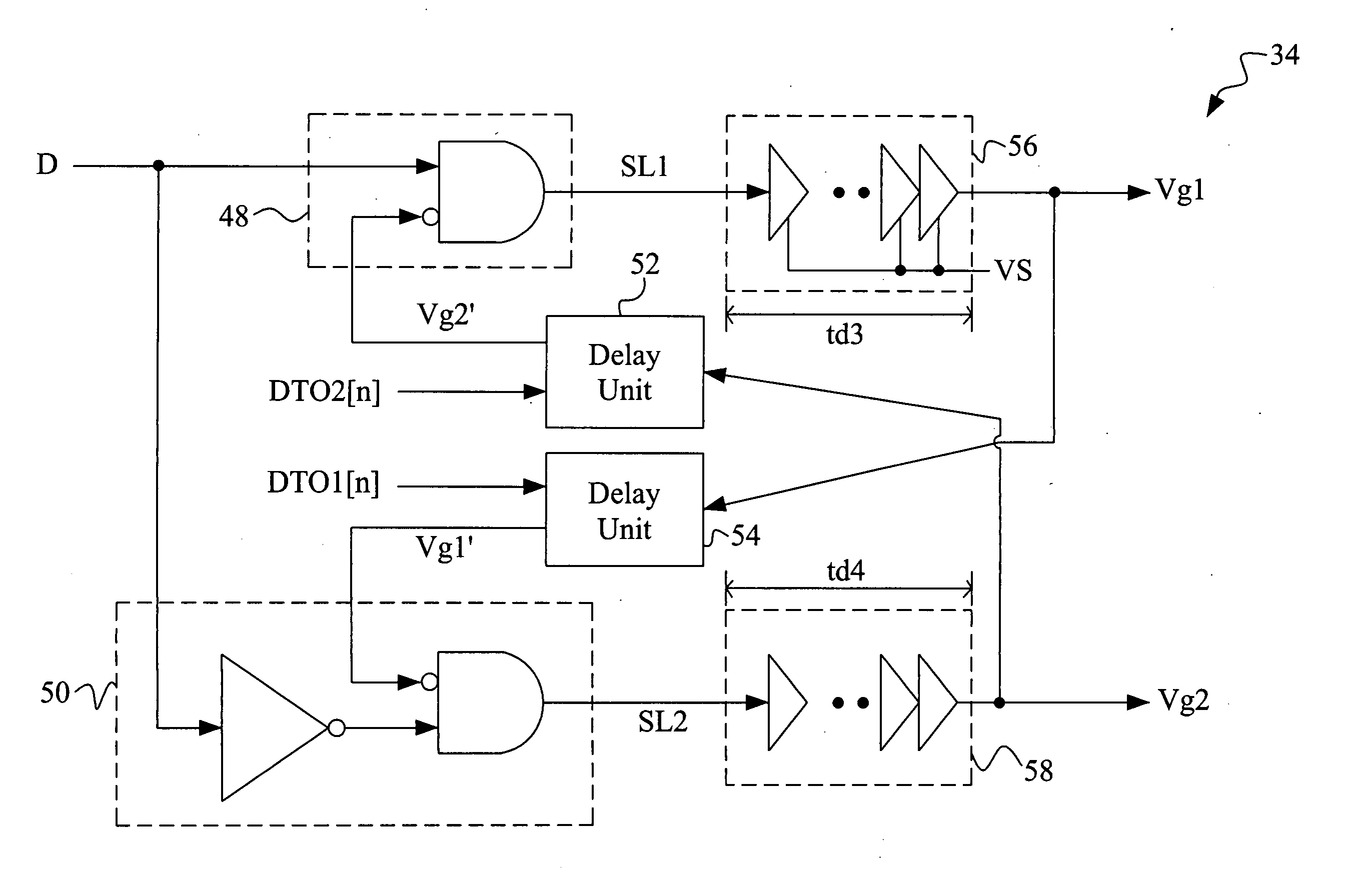
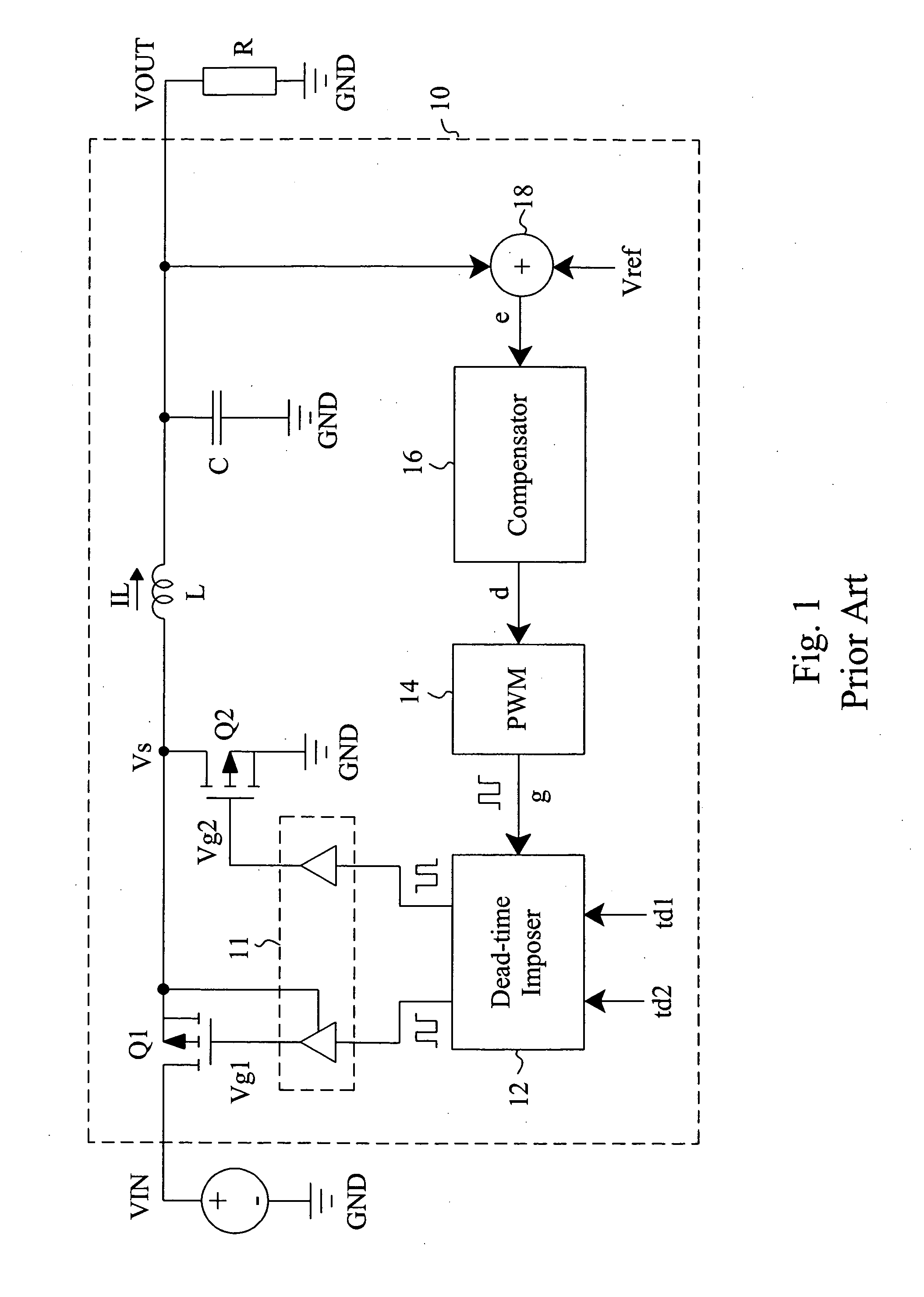
[0014]According to the present invention, as shown in FIG. 3, a digital synchronous switching converter 30 includes a power stage 31 and a control circuit 32 to operate the power stage 31. The control circuit 32 provides driving signals Vg1 and Vg2 to switch a pair of serially connected power switches M1 and M2 in the power stage 31 to convert an input voltage VIN into an output voltage VOUT. In the control circuit 32, a driver 34 generates the driving signals Vg1 and Vg2 according to a pulse width modulation signal D and delay signals DTO1[n] and DTO2[n], a feedback loop 40 detects the output voltage VOUT to generate a digital feedback signal d[n], a digital pulse width modulator 36 generates the pulse width modulation signal D according to the digital feedback signal d[n] for the driver 34 to regulate the output voltage VOUT, and a dead-time optimizer 38 generates the delay signals DTO1[n] and DTO2[n] according to the digital feedback signal d[n] for the driver 34 to dynamically a...
PUM
 Abstract
Description
Claims
Application Information
 - R&D
- Intellectual Property
- Life Sciences
- Materials
- Tech Scout
- Unparalleled Data Quality
- Higher Quality Content
- 60% Fewer Hallucinations
Browse by: Latest US Patents, China's latest patents, Technical Efficacy Thesaurus, Application Domain, Technology Topic, Popular Technical Reports.
© 2025 PatSnap. All rights reserved.Legal|Privacy policy|Modern Slavery Act Transparency Statement|Sitemap|About US| Contact US: help@patsnap.com