Image capture apparatus and control method thereof
- Summary
- Abstract
- Description
- Claims
- Application Information
AI Technical Summary
Benefits of technology
Problems solved by technology
Method used
Image

Examples
first embodiment
[0033]First, the configuration and overall processing operations of an image capture apparatus according to a first embodiment of the present invention will be described, with reference to FIGS. 1 to 5B.
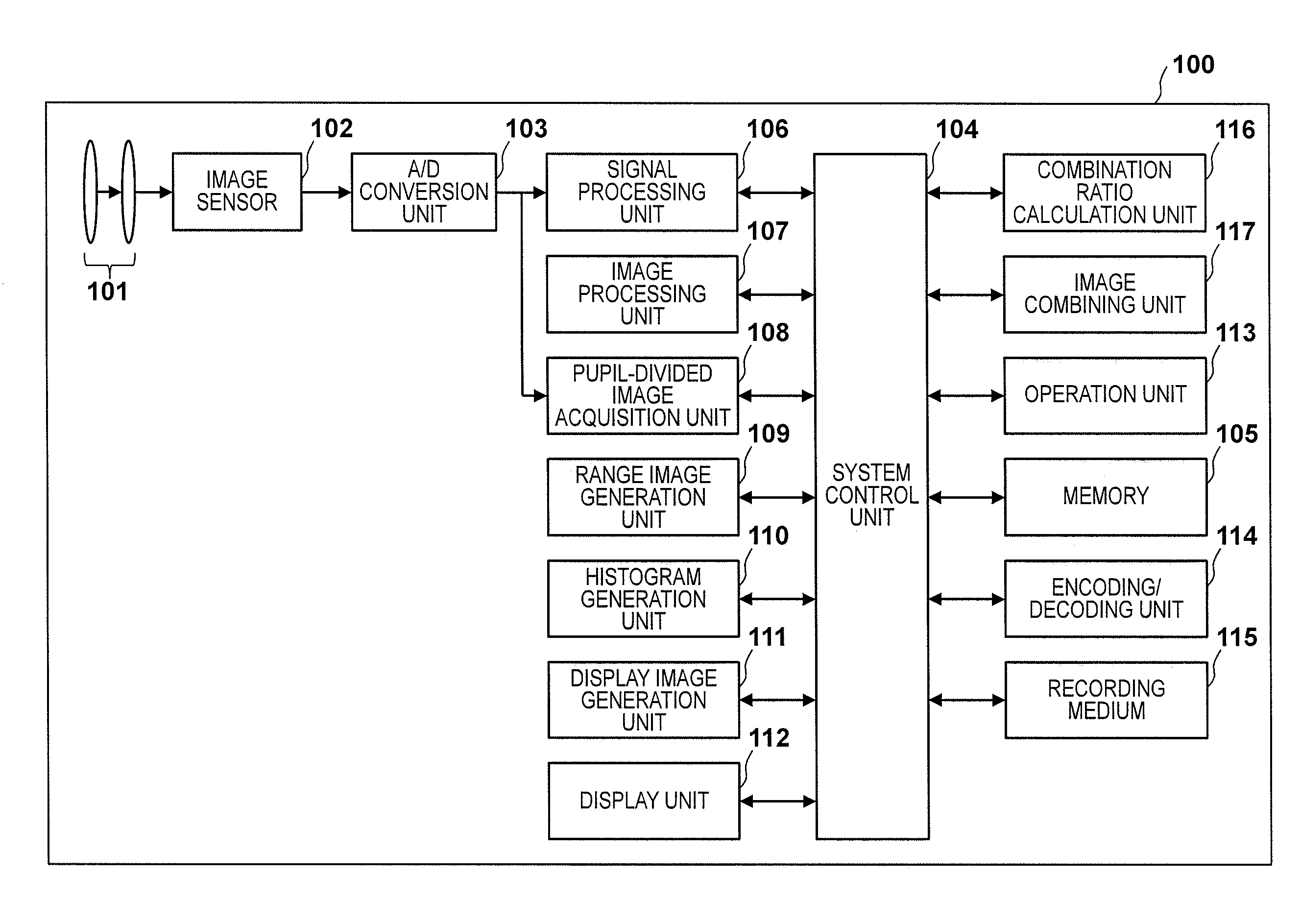
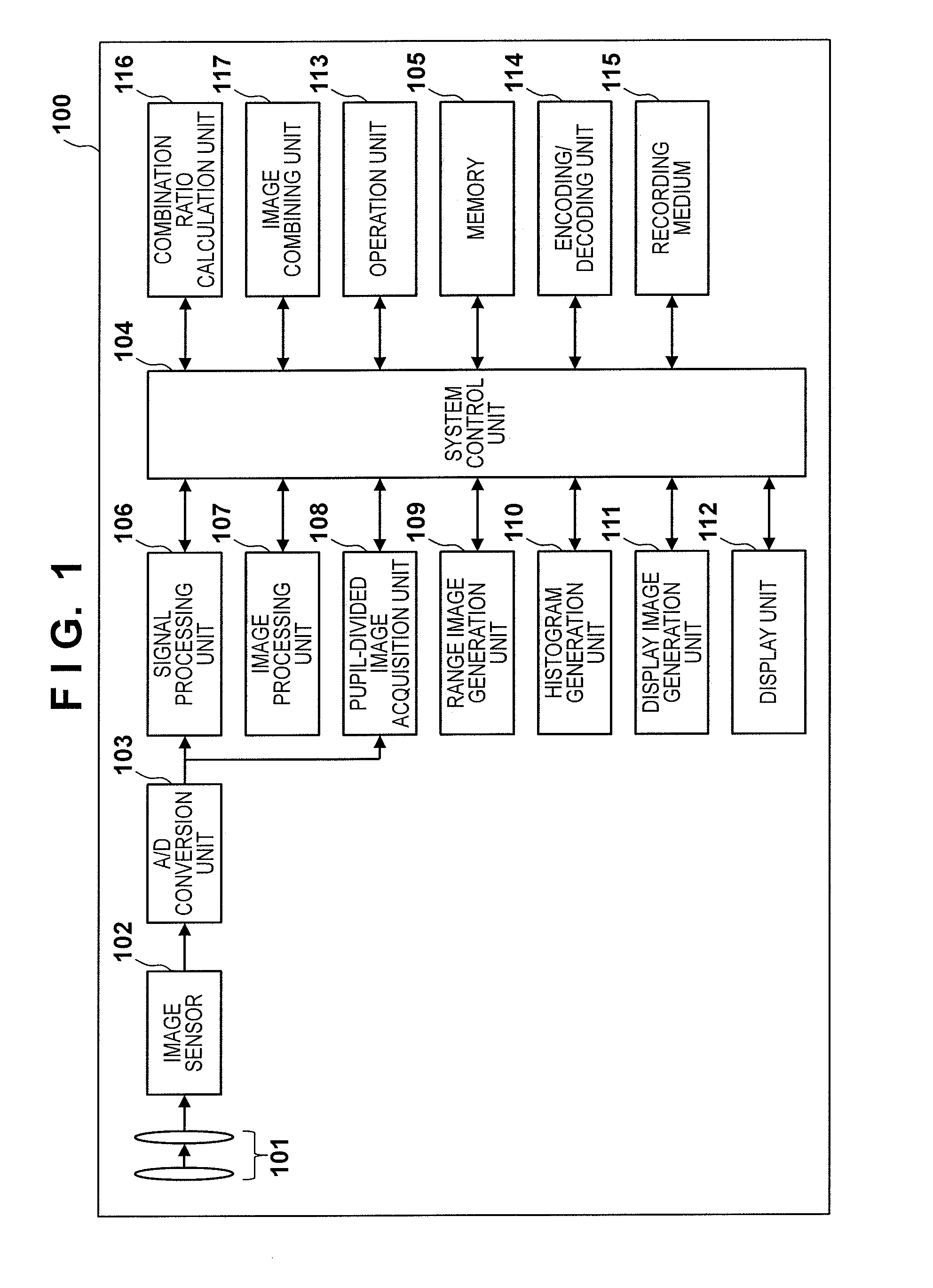
[0034]FIG. 1 is a block diagram schematically showing an exemplary functional configuration of a digital camera serving as an exemplary image capture apparatus according to the first embodiment of the present invention.
[0035]A digital camera 100 may be either a digital still camera or a digital video camera, but is assumed to be a digital still camera in the present embodiment. An image capture optical system 101 is constituted by a group of lenses (hereinafter, “image capture lenses”) including a zoom lens and a focusing lens, and an aperture.
[0036]An image sensor 102 is a CCD image sensor or a CMOS image sensor, for example. The image sensor 102 generates image signals (electrical signals) by photoelectrically converting a subject image formed by the image capture lenses of the ima...
second embodiment
[0107]Next, a second embodiment will be described. The present embodiment differs from the first embodiment in that a subject of interest is detected from a captured image, and priority is given to the focus distance of the subject of interest when capturing a plurality of images. Hereinafter, the present embodiment will be described focusing on the differences from the first embodiment.
[0108]In a digital camera of the present embodiment, the image processing unit 107 has a function of detecting a subject of interest. This detection function may be a function for detecting an image pattern such as a person or a face from a captured image that has undergone signal processing and image processing, or may be a function for detecting an area in which there is large amount of movement or change through comparison with captured images that were captured at different times. Note that a functional block for detecting a subject of interest may be provided separately to the image processing u...
third embodiment
[0115]Next, a third embodiment will be described. The present embodiment differs from the second embodiment in that a distance histogram is generated after having detected a subject of interest from captured images and weighted the area of the detected subject of interest. Hereinafter, description will be given focusing on the differences from the second embodiment.
[0116]The method of determining the focus distance at the time of capturing a plurality of images for generating a combined image having an expanded depth of field according to the present embodiment will be described, with reference to FIGS. 14 to 15B.
[0117]FIG. 14 shows an exemplary captured image that was captured during electronic viewfinder display operation.
[0118]A captured image 1211 is captured at a focus distance of 8 m, and, in contrast to the captured image 711 at a focus distance of 8 m in the first embodiment shown in FIG. 7, there are other persons 604, 605, 607 and 608 around the person 601. These persons 6...
PUM
 Abstract
Description
Claims
Application Information
 - R&D
- Intellectual Property
- Life Sciences
- Materials
- Tech Scout
- Unparalleled Data Quality
- Higher Quality Content
- 60% Fewer Hallucinations
Browse by: Latest US Patents, China's latest patents, Technical Efficacy Thesaurus, Application Domain, Technology Topic, Popular Technical Reports.
© 2025 PatSnap. All rights reserved.Legal|Privacy policy|Modern Slavery Act Transparency Statement|Sitemap|About US| Contact US: help@patsnap.com