Fish Filleting Machine
- Summary
- Abstract
- Description
- Claims
- Application Information
AI Technical Summary
Benefits of technology
Problems solved by technology
Method used
Image

Examples
Embodiment Construction
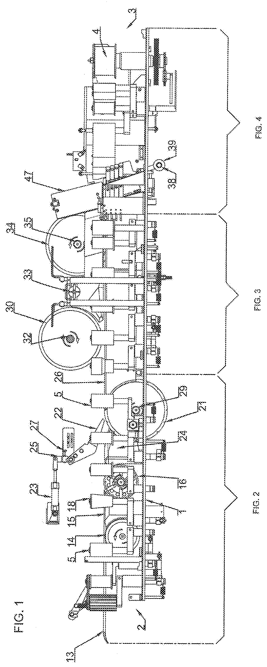
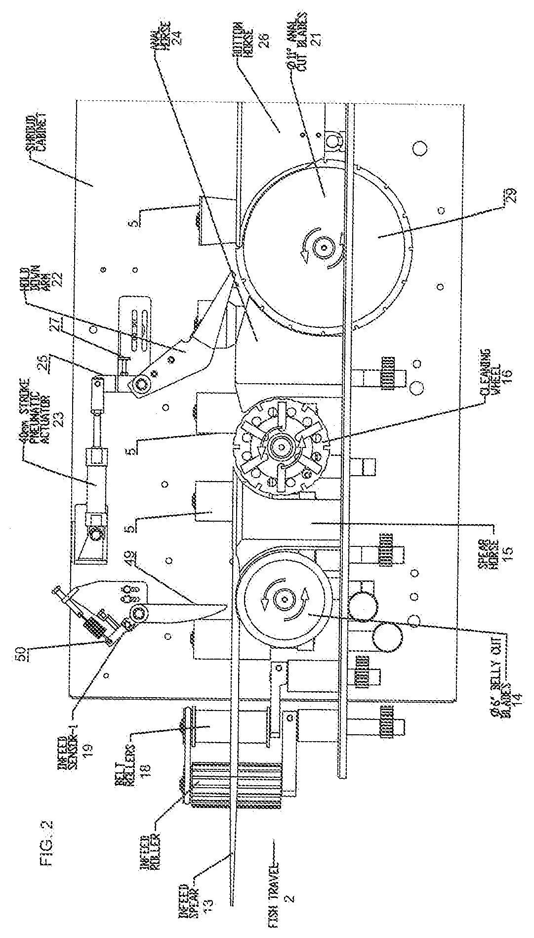
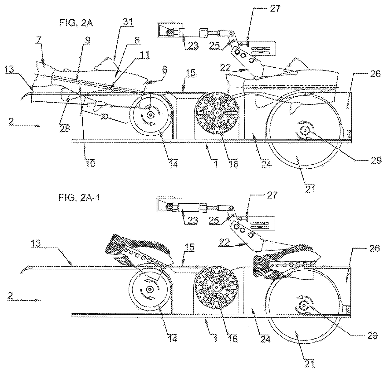
[0027]Referring now to the drawings, FIG. 1 illustrates a fish filleting machine constituting a preferred embodiment of the present invention. The filleting machine includes a frame 1 supported by legs (not shown) having a plurality of work performing stations housed within an enclosure (not shown). The enclosure is generally defined by a rear wall (not shown), the frame 1 and a cover (not shown) which is pivotally mounted to the top of the rear wall. The filleting machine includes an inlet end 2 positioned at the left side as seen in FIG. 1 where headed fish are fed to the machine, and an outlet end 3 located at the right side as seen in FIG. 1 for collecting fish fillets produced by the machine for further processing. A pair of conventional spaced apart feed conveyor belts (not shown) extend along the length of the machine, and are used to transport the fish downstream from inlet end 2 to outlet end 3 along a conveying path to the various work stations of the machine. The conveyin...
PUM
 Abstract
Description
Claims
Application Information
 - R&D
- Intellectual Property
- Life Sciences
- Materials
- Tech Scout
- Unparalleled Data Quality
- Higher Quality Content
- 60% Fewer Hallucinations
Browse by: Latest US Patents, China's latest patents, Technical Efficacy Thesaurus, Application Domain, Technology Topic, Popular Technical Reports.
© 2025 PatSnap. All rights reserved.Legal|Privacy policy|Modern Slavery Act Transparency Statement|Sitemap|About US| Contact US: help@patsnap.com