Flywheel arrangement with an added mass
- Summary
- Abstract
- Description
- Claims
- Application Information
AI Technical Summary
Benefits of technology
Problems solved by technology
Method used
Image

Examples
Embodiment Construction
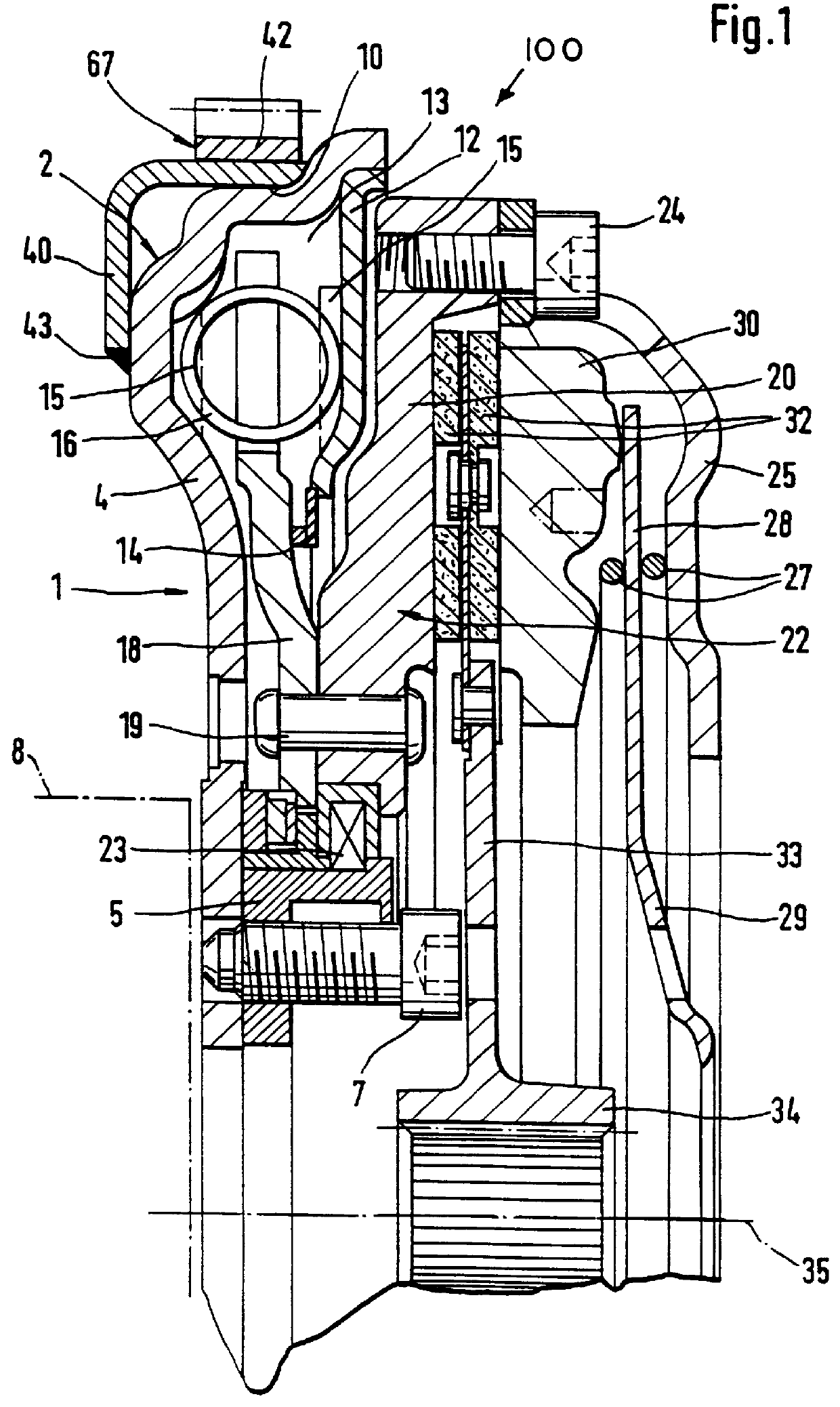
Referring initially to FIG. 1, a flywheel arrangement 100 includes a transmission element 1 on its drive side in the form of a flywheel 2. The flywheel 2 has a primary flange 4 which extends on the radial outer side of the flywheel 2. A radial inner end of flywheel 2 is connected with a hub 5 by fastening means 7 which further serve to connect the flywheel arrangement 100 to a crankshaft 8 (shown schematically in dash-dot lines) of a driving means, such as for example, an internal combustion engine (not shown).
The primary flange 4 comprises an axial portion 10 in its outer circumferential area. A cover plate 12 extends radially inward and is fastened to this axial portion 10. A grease chamber 13 which is filled at least partially with viscous medium is formed axially between the primary flange 4 and the cover plate 12. Elastic elements 16 of a torsional vibration damper are inserted within the grease chamber 3. These elastic elements 16 are controllable by control elements 15 that a...
PUM
 Abstract
Description
Claims
Application Information
 - R&D
- Intellectual Property
- Life Sciences
- Materials
- Tech Scout
- Unparalleled Data Quality
- Higher Quality Content
- 60% Fewer Hallucinations
Browse by: Latest US Patents, China's latest patents, Technical Efficacy Thesaurus, Application Domain, Technology Topic, Popular Technical Reports.
© 2025 PatSnap. All rights reserved.Legal|Privacy policy|Modern Slavery Act Transparency Statement|Sitemap|About US| Contact US: help@patsnap.com