Putter stabilizing brace for putt training
- Summary
- Abstract
- Description
- Claims
- Application Information
AI Technical Summary
Benefits of technology
Problems solved by technology
Method used
Image

Examples
Embodiment Construction
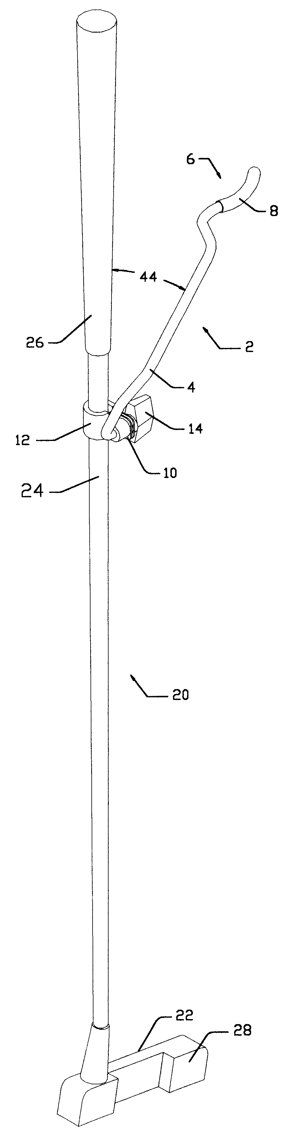
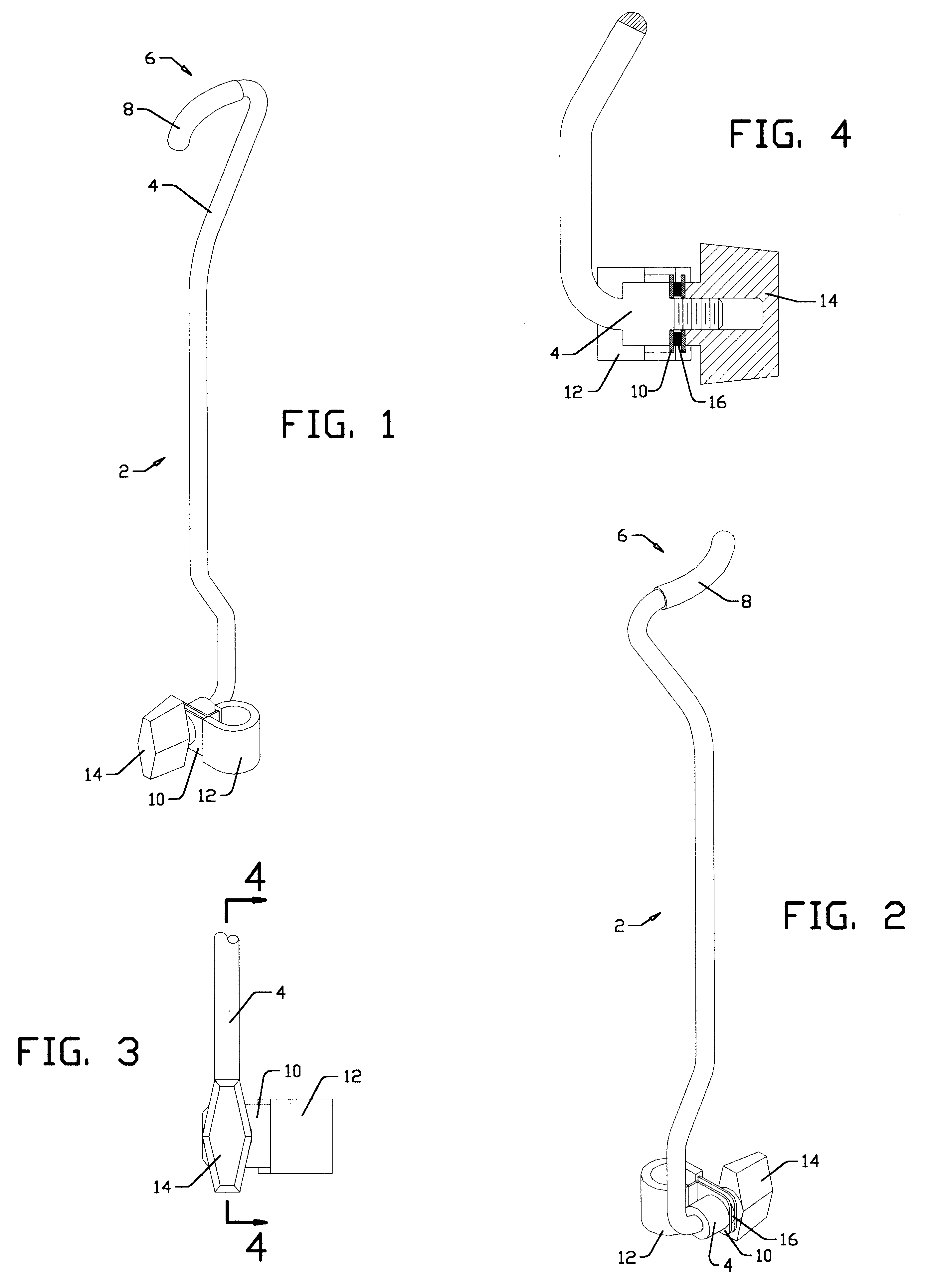
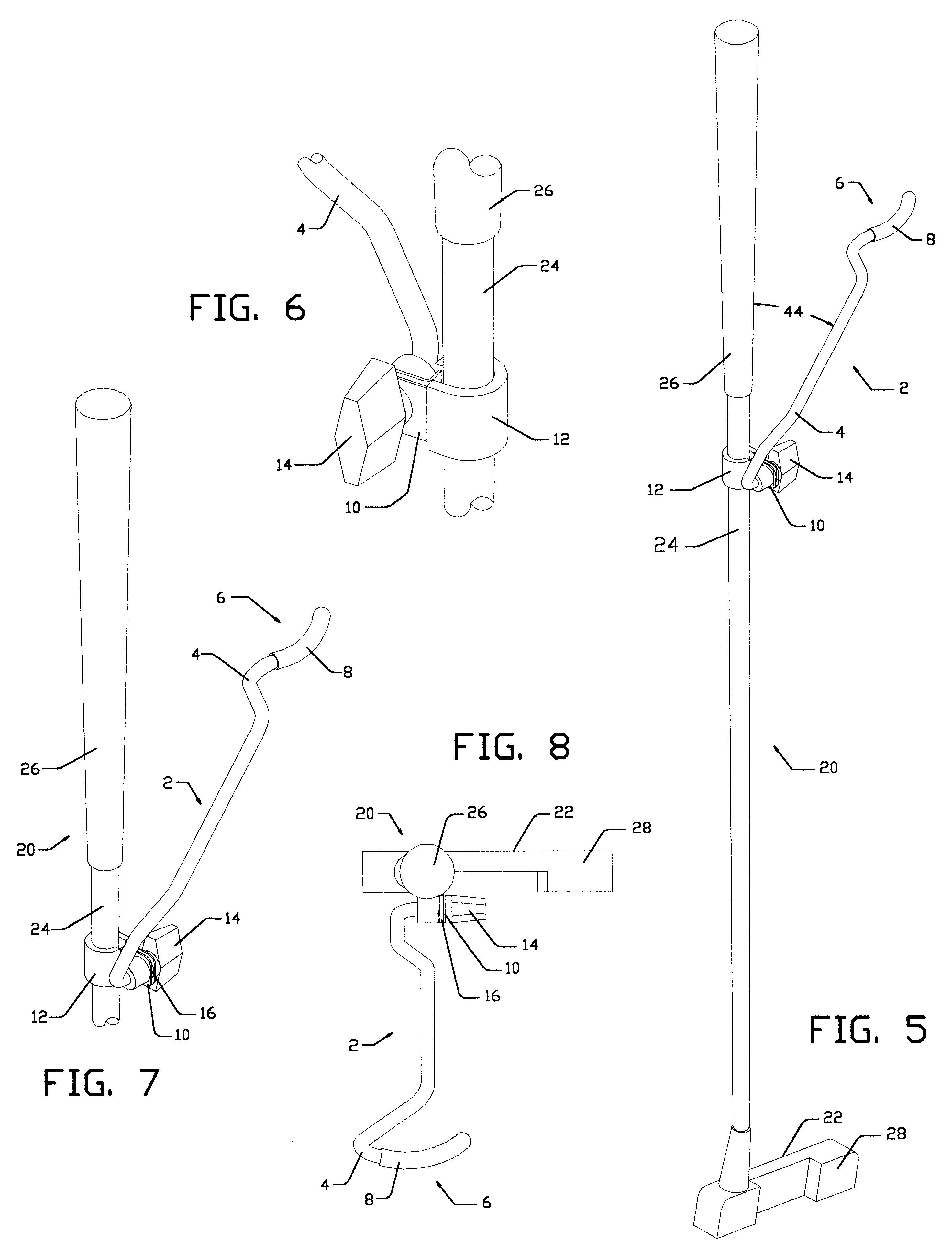
A typical embodiment of the putt stabilizer 2 is shown in FIGS. 1, 2, 3, and 4. It consists of a flat, c-shaped shaft clamp 10 at its base used to attach stabilizer 2 to a putter 20 (FIG. 5). Most putter shafts 24 have a diameter of about a half an inch (1 / 2) near the grip; therefore, clamp 10 is sized accordingly. A protective rubber clamp pad 12 insulates clamp 10 from marring shaft 24. Clamp 10 has a clearance hole at the end of each leg, providing a means for a threaded fastener to pass through.
A round stabilizer bar 4 having an external threaded end and shoulder, extends through the clearance holes in clamp 10 until stopped by the shoulder located just above its threaded end (FIG. 4). A 1 / 4" diameter aluminum rod has been found to be an adequate material for the construction of bar 4. An internal threaded knob 14 is threaded onto the portion of bar 4 extending through clamp 10. As the knob is threaded onto bar 4, the legs of clamp 10 are drawn together, decreasing its internal ...
PUM
 Abstract
Description
Claims
Application Information
 - R&D
- Intellectual Property
- Life Sciences
- Materials
- Tech Scout
- Unparalleled Data Quality
- Higher Quality Content
- 60% Fewer Hallucinations
Browse by: Latest US Patents, China's latest patents, Technical Efficacy Thesaurus, Application Domain, Technology Topic, Popular Technical Reports.
© 2025 PatSnap. All rights reserved.Legal|Privacy policy|Modern Slavery Act Transparency Statement|Sitemap|About US| Contact US: help@patsnap.com