Non-powered trailed switch detector for railroad track switching equipment
a switch detector and track switching technology, which is applied in the direction of point operation from vehicles, railway signalling, railway signalling and safety, etc., can solve the problems of derailing a rail vehicle passing, adding some expense and complexity to the switching arrangement, and destroying the switch machine which holds the point rails in position
- Summary
- Abstract
- Description
- Claims
- Application Information
AI Technical Summary
Benefits of technology
Problems solved by technology
Method used
Image

Examples
first embodiment
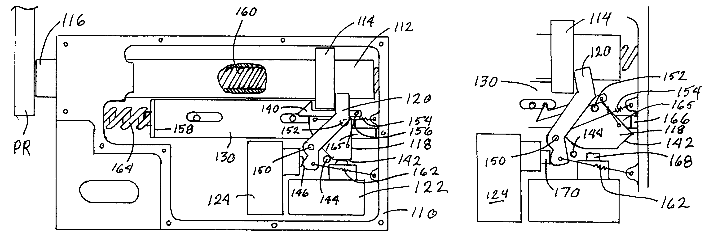
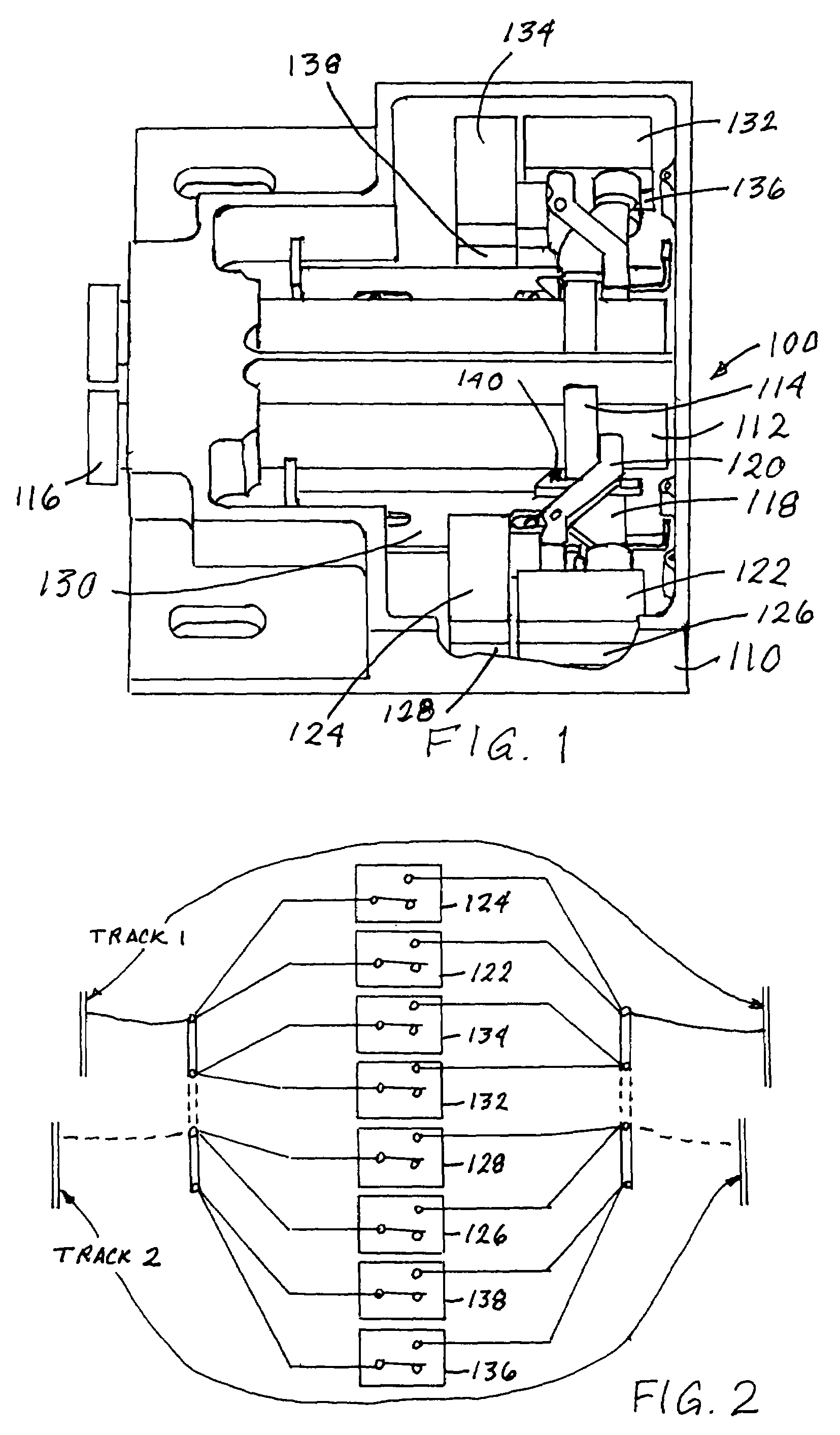
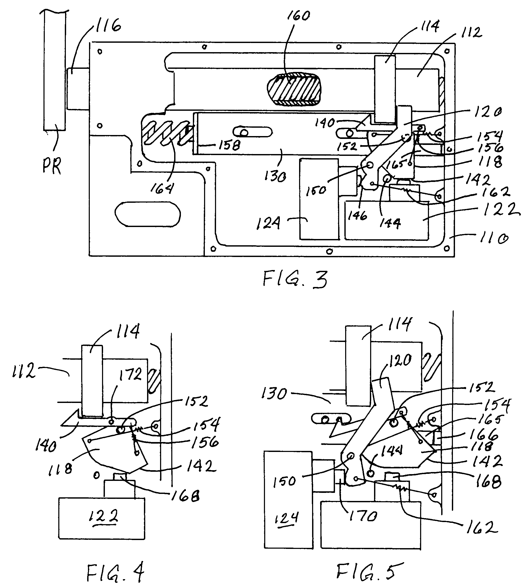
[0025]As shown in FIG. 1, the apparatus 100 of the present invention includes a housing 110 in which are mounted one or more point rail follower pistons 112. A collar 114 is fixedly mounted on each follower piston 112, and a distal end 116 of each follower piston 112 is adapted to remain in contact with and follow a point rail PR, as shown in FIG. 3. Only half of the apparatus 100 is shown in FIG. 3, for simplicity. FIG. 3 also shows that a spring 160 can be used to bias the follower piston 112 to remain in contact with the point rail PR.
[0026]An actuator cam 118 is positioned to interact with the collar 114 on each follower piston 112, and each actuator cam 118 selectively opens a pair of trailing move detector switches 122, 126 or 132, 136. A circuit controller lever 120 can also be provided for each follower piston 112, with each circuit controller lever 120 actuating a pair of circuit controller switches 124, 128 or 134, 138. As shown in FIG. 2, the trailing move detector switch...
second embodiment
[0031]In the apparatus 200 shown in FIG. 6, a follower block 214 is mounted to the point rail follower piston 212. A contact base 246 is mounted to the housing 210, with a trailing move detector switch 250 mounted to the contact base 246. The trailing move detector switch 250 can be, for example, a simple circuit board with a flexible contact arm 252 biased toward the circuit board. When the contact arm 252 contacts the switch 250, the switch is closed. An actuator pawl 216 is pivotably mounted on a pawl shaft 224 on the follower block 214. A suitable mechanism for providing a biasing force, such as a pawl spring 226 biases the actuator pawl 216 in the counter-clockwise direction. A latch 230 is pivotably mounted on a latch post 238 to the follower block 214. A latch spring 236 biases the latch 230 in the counter-clockwise direction. FIG. 6 shows the apparatus 200 in its “reset” position, with the trailing move detector switch 250 open, corresponding to the farthest right position o...
PUM
 Abstract
Description
Claims
Application Information
 - R&D
- Intellectual Property
- Life Sciences
- Materials
- Tech Scout
- Unparalleled Data Quality
- Higher Quality Content
- 60% Fewer Hallucinations
Browse by: Latest US Patents, China's latest patents, Technical Efficacy Thesaurus, Application Domain, Technology Topic, Popular Technical Reports.
© 2025 PatSnap. All rights reserved.Legal|Privacy policy|Modern Slavery Act Transparency Statement|Sitemap|About US| Contact US: help@patsnap.com