Planar broadband traveling-wave beam-scan array antennas
- Summary
- Abstract
- Description
- Claims
- Application Information
AI Technical Summary
Benefits of technology
Problems solved by technology
Method used
Image

Examples
experimental verification
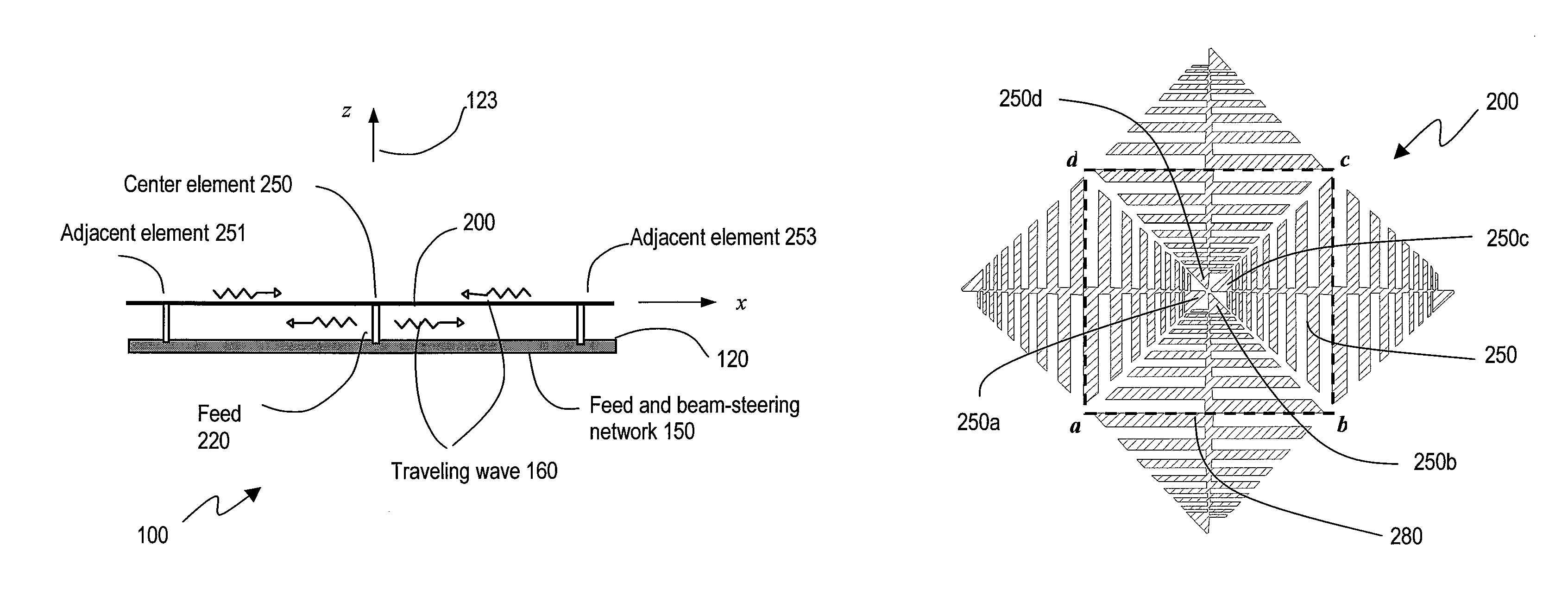
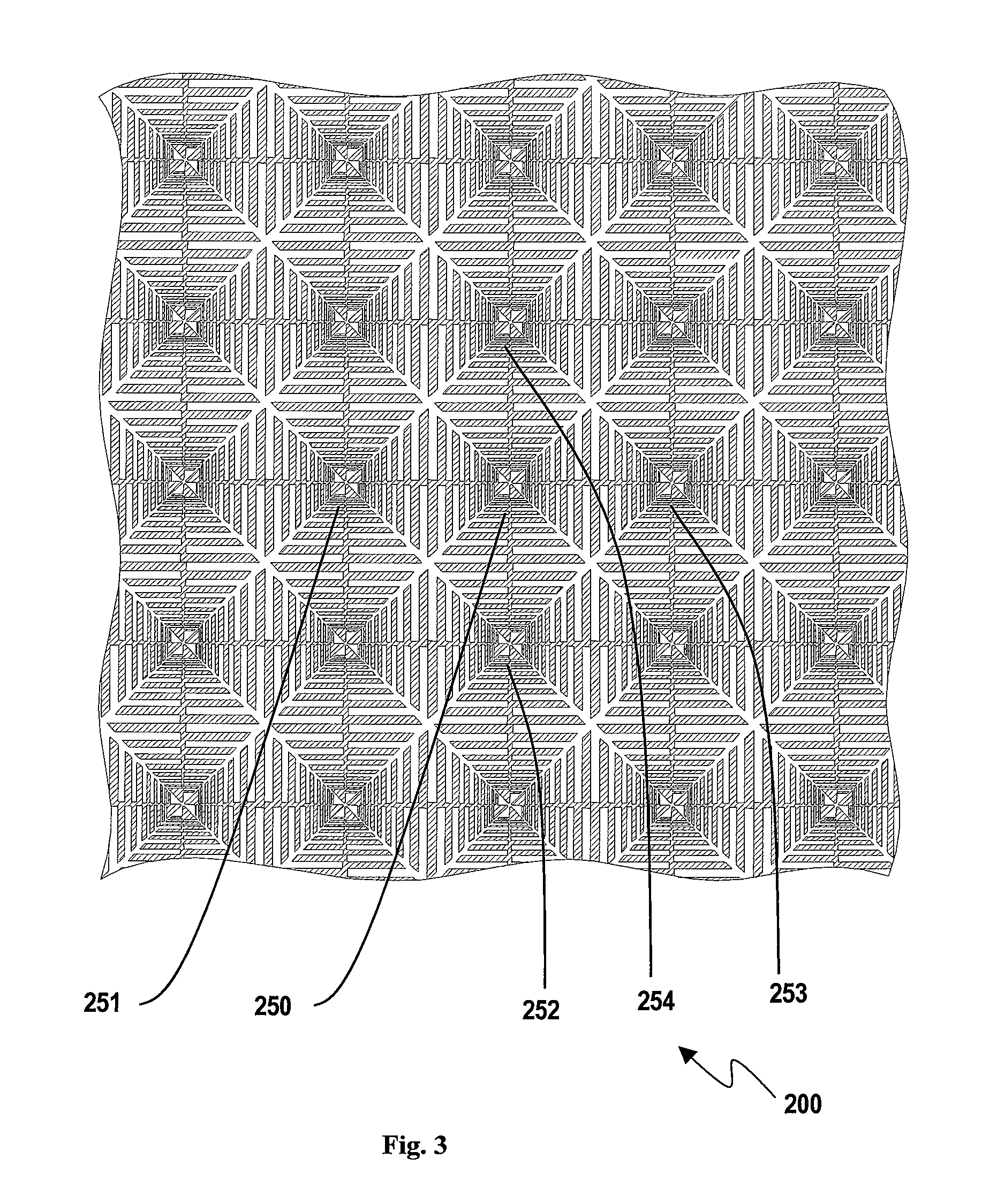
[0052]Basic experimentation has been performed for this invention. A breadboard 5×5-cell planar array similar to that in FIGS. 3-5 was designed, fabricated, and tested. Each cell has both x and y directed LP planar dipoles. The vertical center element has a broadband balun feed across its feed terminals (corresponding to 250b and 250d in FIG. 5). Each of the other 24 vertical LP dipoles has a 100-ohm resistor load. All the 25 horizontal LP dipoles have their feed terminals (corresponding to 250a and 250c in FIG. 5) floating (open-circuit with no connection to other element or device).
[0053]According to the theory and practices in planar arrays, the properties of a large planar array can be determined by measuring its “active element gain pattern,” which takes account of the mutual coupling and beam scan of a planar array (Mailloux, 1994; Pozar, 1994). The active gain pattern reveals the scan property of the element antenna, including both impedance matching and radiation pattern. Th...
PUM
 Abstract
Description
Claims
Application Information
 - R&D
- Intellectual Property
- Life Sciences
- Materials
- Tech Scout
- Unparalleled Data Quality
- Higher Quality Content
- 60% Fewer Hallucinations
Browse by: Latest US Patents, China's latest patents, Technical Efficacy Thesaurus, Application Domain, Technology Topic, Popular Technical Reports.
© 2025 PatSnap. All rights reserved.Legal|Privacy policy|Modern Slavery Act Transparency Statement|Sitemap|About US| Contact US: help@patsnap.com