Belt for continuously variable transmission
- Summary
- Abstract
- Description
- Claims
- Application Information
AI Technical Summary
Benefits of technology
Problems solved by technology
Method used
Image

Examples
Embodiment Construction
[0025] The mode for carrying out the present invention will now be described by way of embodiments of the present invention shown in the accompanying drawings.
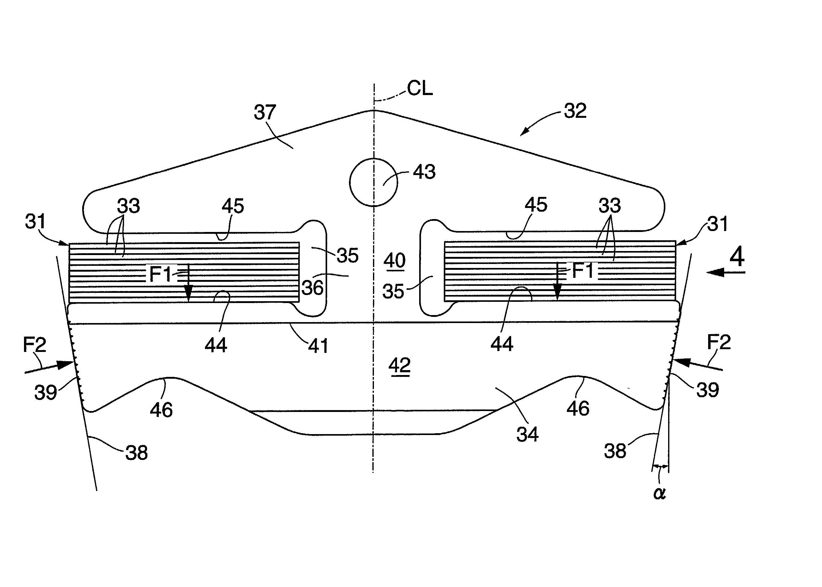
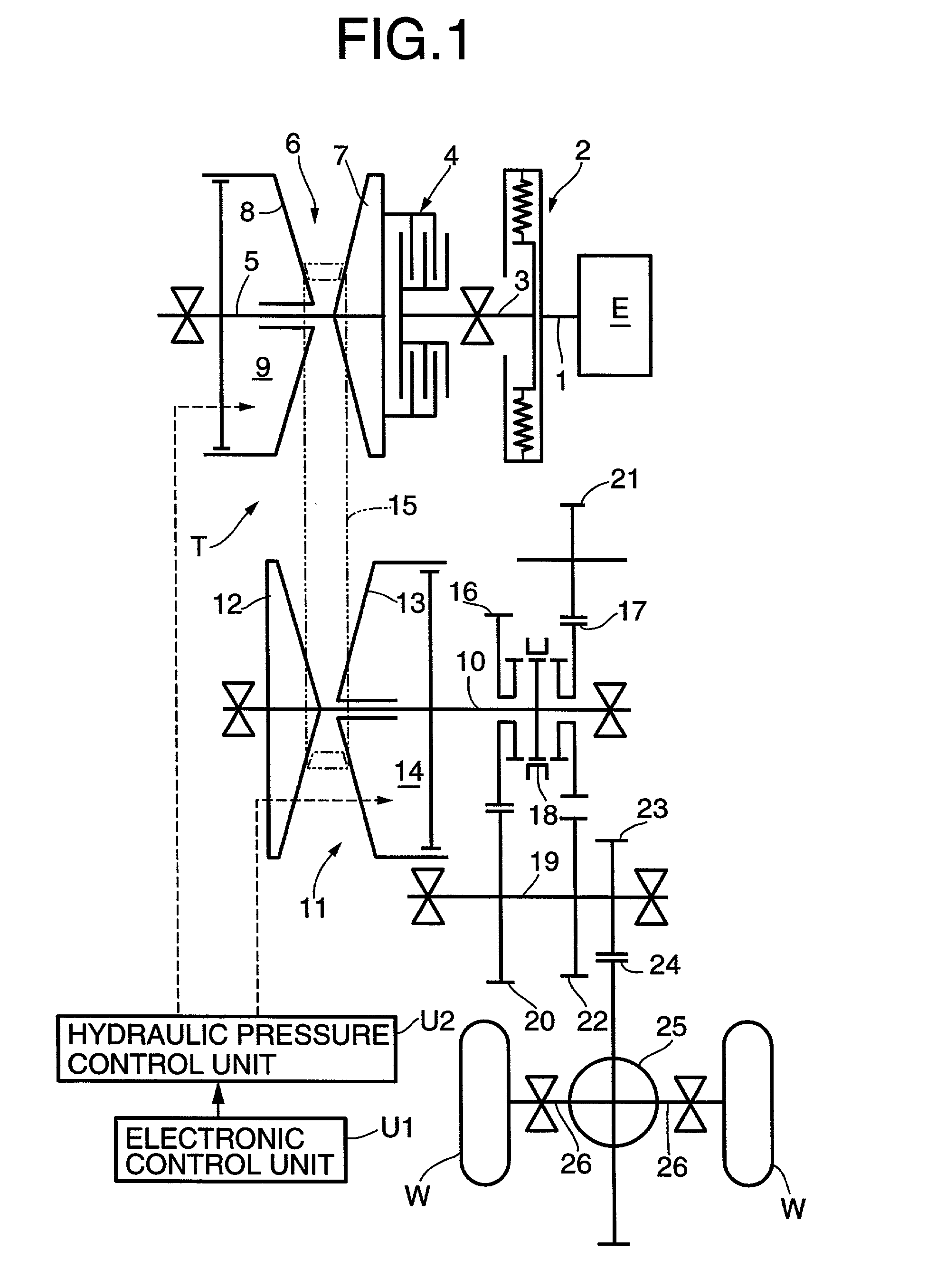
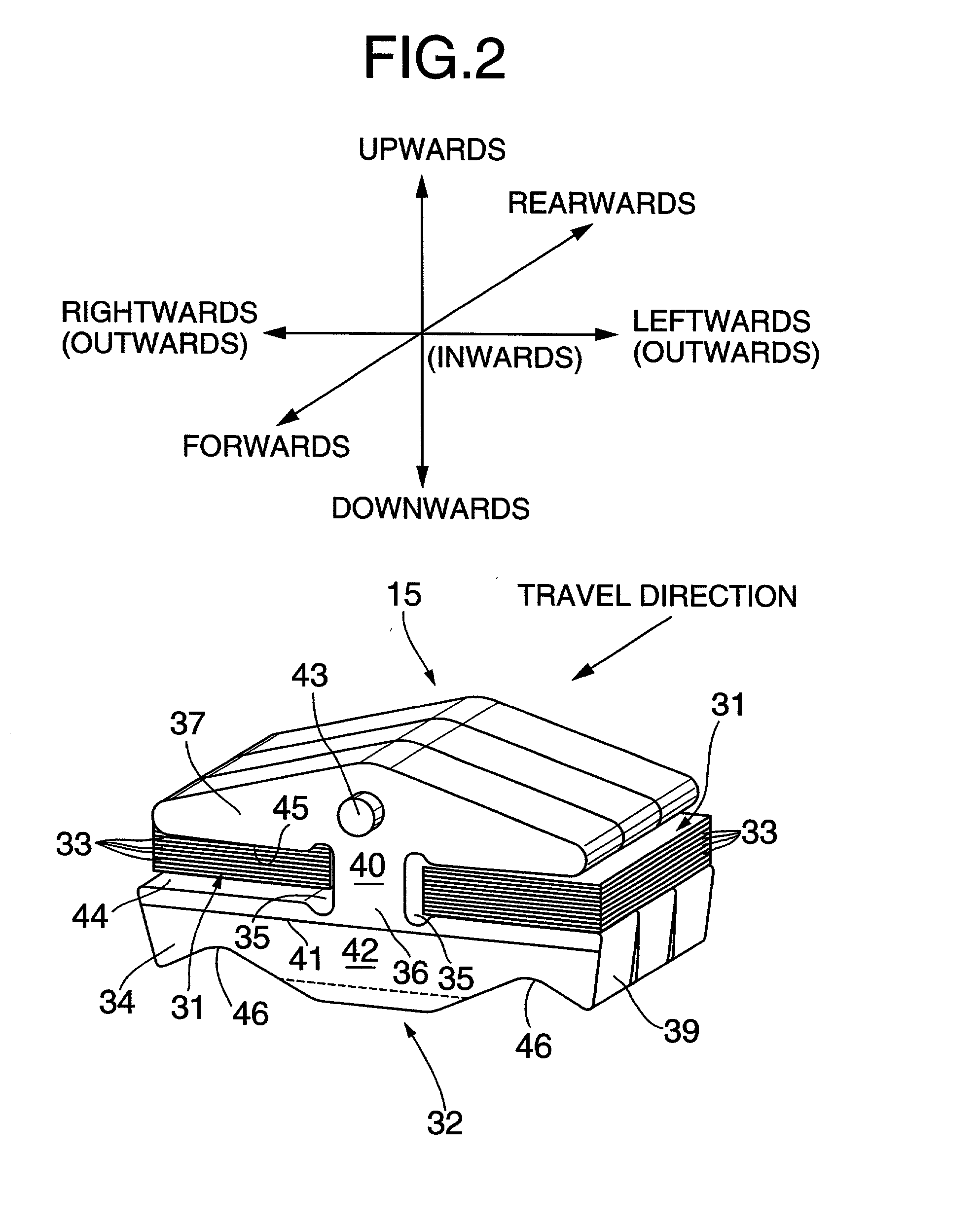
[0026] FIGS. 1 to 9 show a first embodiment of the present invention. FIG. 1 is a skeletal diagram of a power-transmitting system in a vehicle provided with a continuously variable transmission; FIG. 2 is a partially perspective view of a metal belt; FIG. 3 is a front view of a metal element; FIG. 4 is a view taken in the direction of an arrow 4 in FIG. 3; FIG. 5 is an enlarged view of an essential portion shown in FIG. 3; FIGS. 6A and 6B are diagrams showing deformation of the metal element due to a load; FIGS. 7A and 7B are diagrams showing the distribution of a bending moment applied to a saddle face; FIG. 8 is a graph showing ranges of the height Hv of a V-face and the height Hs of an upper non-contact portion in which the parallelism of the V-face is lower than .+-.1 .mu.m; and FIG. 9 is a graph showing the relationship b...
PUM
 Abstract
Description
Claims
Application Information
 - R&D
- Intellectual Property
- Life Sciences
- Materials
- Tech Scout
- Unparalleled Data Quality
- Higher Quality Content
- 60% Fewer Hallucinations
Browse by: Latest US Patents, China's latest patents, Technical Efficacy Thesaurus, Application Domain, Technology Topic, Popular Technical Reports.
© 2025 PatSnap. All rights reserved.Legal|Privacy policy|Modern Slavery Act Transparency Statement|Sitemap|About US| Contact US: help@patsnap.com