Fuel Injector
- Summary
- Abstract
- Description
- Claims
- Application Information
AI Technical Summary
Benefits of technology
Problems solved by technology
Method used
Image

Examples
Embodiment Construction
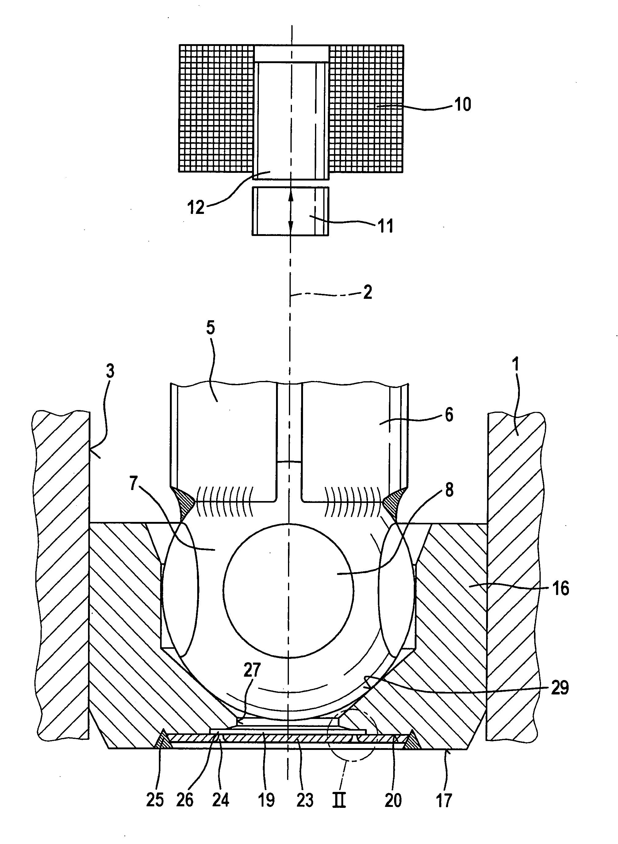
[0010]FIG. 1 shows as an exemplary embodiment a partial view of a valve in the form of a fuel injector for fuel injection systems of mixture-compressing, externally ignited internal combustion engines. The fuel injector has a tubular valve-seat support 1, indicated only schematically, which constitutes part of a valve housing and in which a longitudinal opening 3 is formed concentrically to a longitudinal valve axis 2. Situated in longitudinal opening 3 is, for example, a tubular valve needle 5, which is fixedly joined at its downstream end 6 to a spherical valve closure member 7, for instance, at whose periphery five flattened regions 8, for example, are provided for the fuel to flow past.
[0011]The fuel injector is actuated in a known manner, e.g. electromagnetically. A schematically sketched electromagnetic circuit, which includes a magnetic coil 10, an armature 11 and a core 12, is used for axial displacement of valve needle 5, and thus for opening the fuel injector against the s...
PUM
 Abstract
Description
Claims
Application Information
 - R&D
- Intellectual Property
- Life Sciences
- Materials
- Tech Scout
- Unparalleled Data Quality
- Higher Quality Content
- 60% Fewer Hallucinations
Browse by: Latest US Patents, China's latest patents, Technical Efficacy Thesaurus, Application Domain, Technology Topic, Popular Technical Reports.
© 2025 PatSnap. All rights reserved.Legal|Privacy policy|Modern Slavery Act Transparency Statement|Sitemap|About US| Contact US: help@patsnap.com