Trigger grip
- Summary
- Abstract
- Description
- Claims
- Application Information
AI Technical Summary
Benefits of technology
Problems solved by technology
Method used
Image

Examples
Embodiment Construction
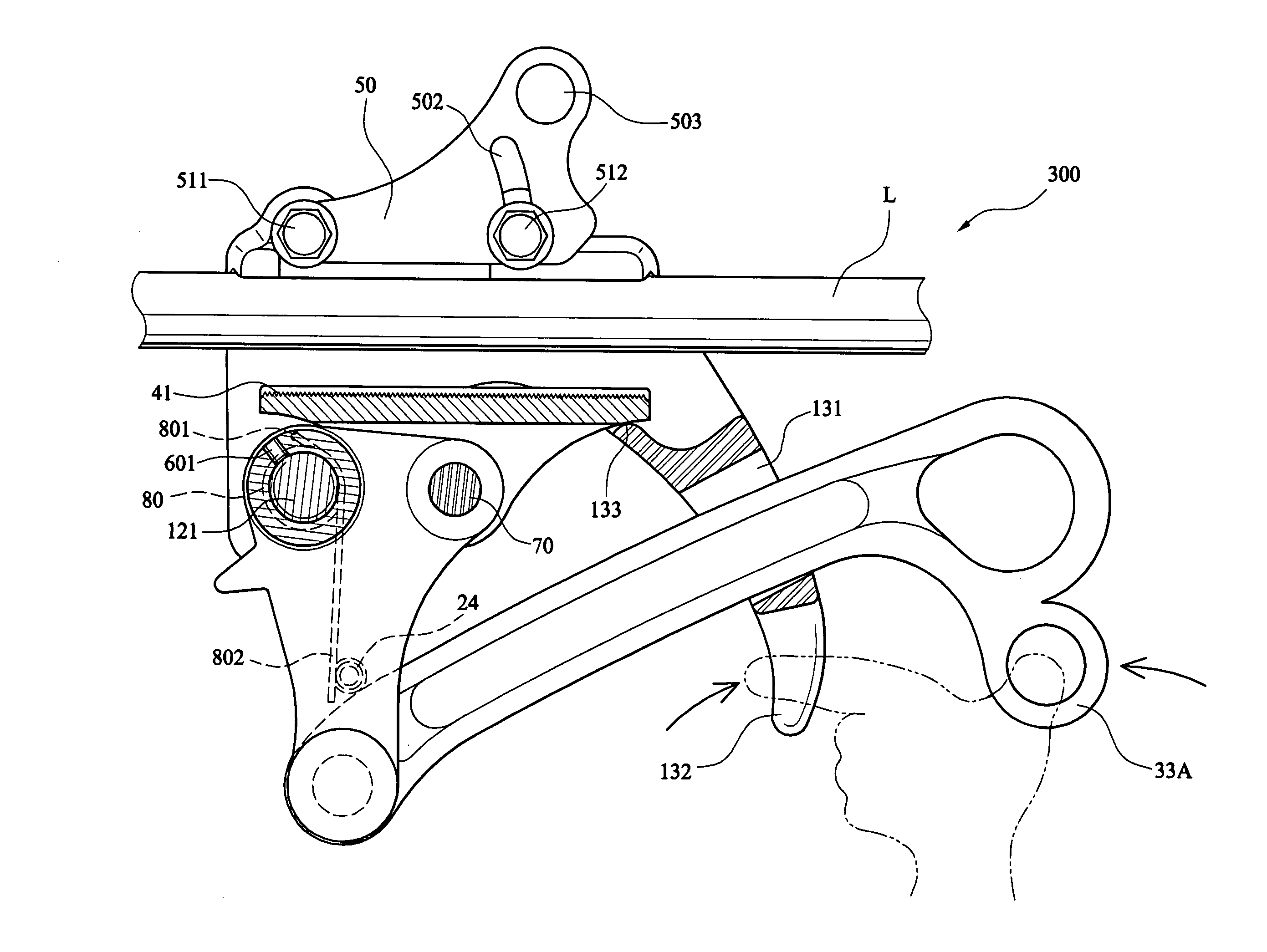
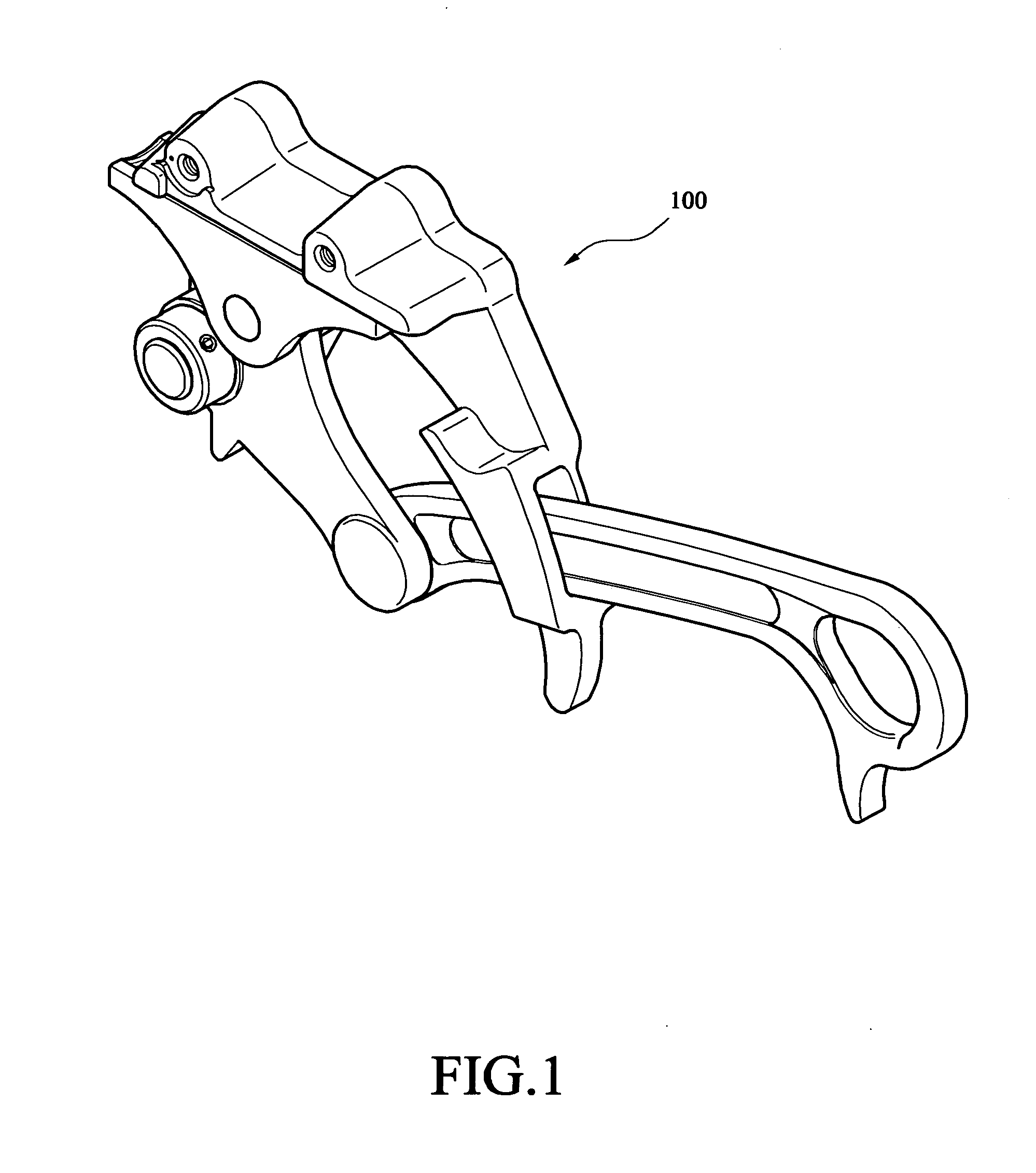
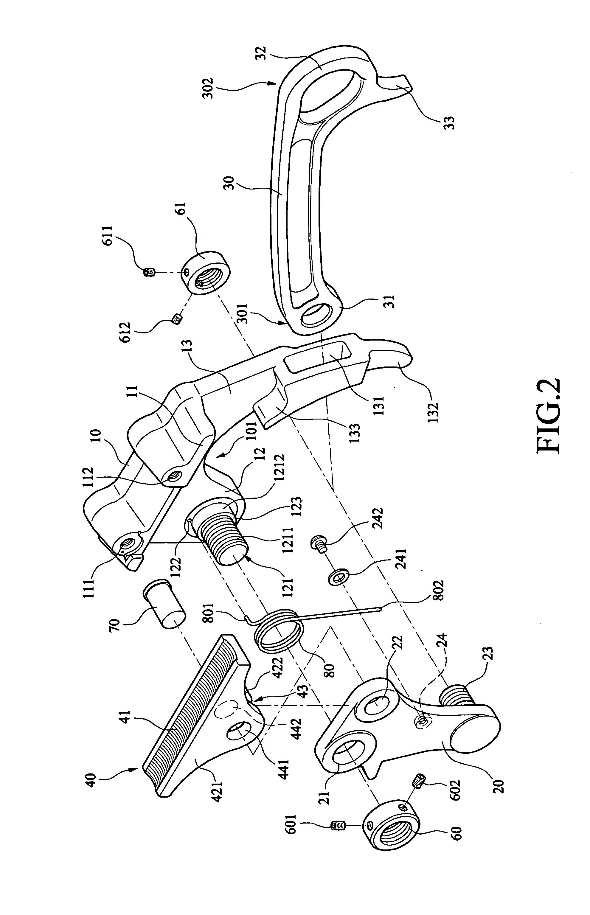
[0029]Referring to FIGS. 1 to 9, a trigger grip 100 in accordance with a first preferred embodiment of the invention comprises a body 10, a pivotal link 20, a lever 30, a gripping seat 40 and a pivotal plate 50 each discussed in detail below.
[0030]The body 10 comprises a curved bottom recess 101, an upper jaw 11 extending laterally, and two spaced threaded holes 111, 112 on top of the upper jaw 11. The body 10 further comprises a pivot section 12 provided on one side of the recess 101 and a sleeve section 13 provided on the other side of the recess 101. The pivot section 12 comprises a solid, stepped-diameter, cylindrical projection 121 projecting laterally. A positioning hole 122 is provided on the pivot section 12 proximate an enlarged base 1212 of the projection 121. The projection 121 further comprises external threads 1211 and a shoulder 123 at a joining portion of the threads 1211 and the base 1212. The provision of the projection 121 can prevent the body 10 from being adverse...
PUM
 Abstract
Description
Claims
Application Information
 - R&D
- Intellectual Property
- Life Sciences
- Materials
- Tech Scout
- Unparalleled Data Quality
- Higher Quality Content
- 60% Fewer Hallucinations
Browse by: Latest US Patents, China's latest patents, Technical Efficacy Thesaurus, Application Domain, Technology Topic, Popular Technical Reports.
© 2025 PatSnap. All rights reserved.Legal|Privacy policy|Modern Slavery Act Transparency Statement|Sitemap|About US| Contact US: help@patsnap.com